

_VUKVylScyg.jpg?auto=compress%2Cformat&w=900&h=675&fit=min)
Hardware components | ||||||
 |
| × | 1 | |||
 |
| × | 1 | |||
 |
| × | 1 | |||
 |
| × | 1 | |||
 |
| × | 1 | |||
Software apps and online services | ||||||
 |
| |||||
| ||||||
Hand tools and fabrication machines | ||||||
 |
| |||||
We have seen lots of project involving the awesome Creator pro board from RAK wireless. The Ameba arduino project really makes the board a versatile option for many use case.
Today we will see how to integrate the Creator pro board with the Blynk web services. Blynk is easily one of the most popular mobile app for the IOT. Works with anything: ESP8266, Arduino, Raspberry Pi, SparkFun and others.
According to Blynk:
Blynk is a Platform with iOS and Android apps to control Arduino, Raspberry Pi and the likes over the Internet.
It's a digital dashboard where you can build a graphic interface for your project by simply dragging and dropping widgets.
It's really simple to set everything up and you'll start tinkering in less than 5 mins.
Blynk is not tied to some specific board or shield. Instead, it's supporting hardware of your choice. Whether your Arduino or Raspberry Pi is linked to the Internet over Wi-Fi, Ethernet or this new ESP8266 chip, Blynk will get you online and ready for the Internet Of Your Things.
To get started with the tutorial we have a few simple pre requisites;
- 1) Create an account in BLynk. Also install their app(android or ios) and keep the devices ready with you
- 2) Install the Ameba Arduino Environment by following the instruction here:
https://github.com/Ameba8195/Arduino
I have also explained about the installation in a little detail here as well:
https://www.hackster.io/naresh-krish/diy-remote-wifi-switch-using-the-rak-dashbutton-09b0de
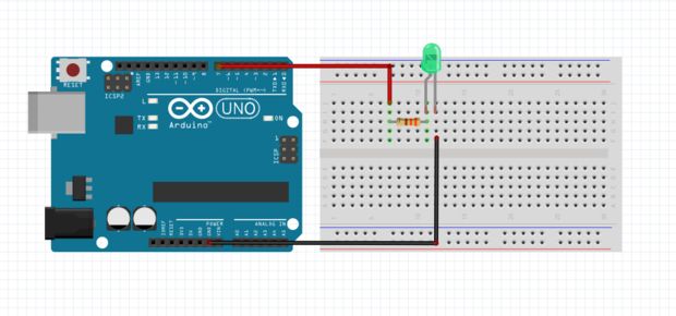
Also have a small led hooked up to a 1k ohm resistor and a few jumper cables handy as well.
As shown in the image above, just connect the positive of the LED to D13 (instead of 9) on the Creator Pro instead of the arduino :)
Setup BlynkTo use Blynk with the Arduino IDE follow these instruction:
Blynk library should be installed manually. Follow the instructions:
- Download the latest release .zip file.
- Unzip it. You will notice that archive contains several folders and several libraries.
- Copy all these libraries to your_sketchbook_folder of Arduino IDE. To find the location of your_sketchbook_folder, go to top menu in Arduino IDE: File -> Preferences (if you are using Mac OS - go to Arduino → Preferences)
The structure of your your_sketchbook_folder should now look like this, along with your other sketches (if you have them):
your_sketchbook_folder/libraries/Blynk your_sketchbook_folder/libraries/BlynkESP8266_Lib ... your_sketchbook_folder/tools/BlynkUpdater your_sketchbook_folder/tools/BlynkUsbScript ...
Note that libraries should go to libraries and tools to tools
Create a Blynk projectIn order to connect Blynk App and your hardware, you need an Auth Token.
- Create a new account in Blynk App.
- Create a New Project. Then choose the board and connection you will use.
- After the project was created, we will send you Auth Token over email.
- Check your email inbox and find the Auth Token.
Once you have the auth token proceed to upload the test sketch.
Upload a blynk exampleNow open the Arduino ide, and select the Creator pro board (8711AM) or the
/* Comment this out to disable prints and save space */
#define BLYNK_PRINT Serial

#include <WiFi.h>
#include <WiFiClient.h>
#include <
// You should get Auth Token in the Blynk App.
// Go to the Project Settings (nut icon).
char auth[] = "xxxx";

// Your WiFi credentials.
// Set password to "" for open networks.
char ssid[] = "xxxx";
char pass[] = "xxxx";

void setup()
{
 // Debug console
 Serial.begin(9600);
 pinMode(13, OUTPUT);
 Blynk.begin(auth, ssid, pass);
 Blynk.run();
 randomSeed(analogRead(A0));
}

void loop()
{
 Blynk.virtualWrite(V0, random(30));
 Blynk.virtualWrite(V1, random(30));
 delay(3000);
}

BLYNK_WRITE(V13) //Button Widget is writing to pin V13
{
 int pinData = param.asInt();
 Serial.print("Button is now: ");
 Serial.println(pinData);
 digitalWrite(13, pinData);
}
Lets go over the code in a little detail
#include <WiFi.h>
#include <WiFiClient.h>
#include <
This includes all the necessary files to enable the Blynk API on the device.
char auth[] = "xxxx";
The Auth[] array stores your authentication token that is generated on a per project basis. Copy paste yours in the quotes.
char ssid[] = "xxxx";
char pass[] = "xxxx";
This is you wifi ssid and password. Paste your's in the place of xxxx
 Serial.begin(9600);
 pinMode(13, OUTPUT);
 Blynk.begin(auth, ssid, pass);
 Blynk.run();
Here we start the serial montor at 9600:8N1 mode and also set pin 13 as output to control the led on D13
Also we start the Blynk object and provide it the auth token, ssid and password.
Then we tell the Blynk api to startup on the board.
Note:
I have used a random number to be sent to the blynk app on virtual pin v0 and v1, this is just to emulate temperature reading. However feel free to send a value from LM35 or any other sensor as well via the same method described below:
Blynk.virtualWrite(V0, random(30));
Blynk.virtualWrite(V1, random(30));
delay(3000);
In the loop function we use the Blynk virtualWrite API to send information to virtual pins hosted in the blynk cloud against your project. on virtual pins, you can send any kind of data, integers, strings, characters etc.
Each virtual pin data can be mapped to widgets in the Android/iOS apps. We will see that in detail next
BLYNK_WRITE(V13) //Button Widget is writing to pin V1
{
 int pinData = param.asInt();
 Serial.print("Button is now: ");
 Serial.println(pinData);
 digitalWrite(13, pinData);
}
This is the section of code that gets executed when a button on virtual pin 13 is pressed. when that happens on the app, the blynk api calls this function and then we get the data from the virtual pin as 1 or 0 via the params.asInt() funtion, we can then use the data and set it to the digital pin 13 via the normal digitalWrite function in Arduino.
Now your all set to showcase your data on the Android/iOS app, lets begin
On the APP....Here we will consider an android app, but the procedure is the same in iOS as well.
Open the project you created for getting the auth token:
- Create a superchart a value widget and a button widget on the project
- Click on the superchart and give it a name.
- Click on the slider icon next to the superchart name and you will see a screen like so:
- Set the INPUT as V0 or virtual pin 0 on the project.
- Similarly click on the Value Display setting and you will see a screen like so.
- Give the PIN allocation on V1 or virtual pin 1 and set the reading rate as PUSH
- Now click on the button widget and you will see a screen as below:
- Set the button on virtual pin 13 as show and set the button on switch mode instead of push mode.
- And now your ready to test the app by clicking the play button on the right hand top on the app project screen.
- Voila, your app now shows the Graph of the random temperature values we were sending to the Blynk services.
- Now try clicking the button widget, when it says on, your led should light up and off would switch off the LED
There are more possibilities with the Blynk app now that you know how to connect widgets to device hardware
To learn more about the blynk API visit the documentation here:
http://docs.blynk.cc/


_M6kErcYJ84.png?auto=compress%2Cformat&w=40&h=40&fit=fillmax&bg=fff&dpr=2)
Comments