The tutorial marks the start of a series of tutorial based on the awesome RAK Wireless iTracker module.
The iTracker module is a very unique board. It hosts a plethora of connectivity options like:
- Nb-IoT provided by the Quectel M35 chipset
- Bluetooth provided by the nordic nrf52832 chipset
- GPS provided by the Quectel L70-R chipset
Not just that a host of on board sensors are available as well:
- Opt 3001 light sensor
- LIS3dh Triple axis accelerometer
- Lis2mdl Triple axis magnetic field sensor
- Bme280 Barometric pressure and temperature sensor
Phew !! that is a lot of connectivity and a lot of sensors for such a small module
Some of the use cases for this module are:
- Vehicle Tracker and fleet management
- Personnel positioning
- Home security
- Safety monitoring for children/elders
- Animal husbandry and protection
The board not only shines in the Hardware but also in its software. it hosts a wide variety of development platforms:
Arduino IDE
- Supports the standard BLEPeripheral Library and Libraries contributed by Adafruit
- Programming support is via SWD interface
Normal development using Nordic SDK
- Supports the NRF SDK v11.0 and above
- Programing support via SWD interface.
Espruino IDE:
- Planned support for Espruino IDE very soon.
- Programming support via USB serial as well as via the BLE UART module wirelessly.
- Can also be programmed from Android or iOS apps
And more are planned :) so stay tuned for the future parts of the tutorial where we will discuss in depth about the various other platform support.
I would also suggest having an Android or iOS device in hand during development to test out the itracker board via the BLE functionality.
Android apps:
- NRF Connect: https://play.google.com/store/apps/details?id=no.nordicsemi.android.mcp&hl=en
- NRF Toolbox: https://play.google.com/store/apps/details?id=no.nordicsemi.android.nrftoolbox&hl=en
iOS Apps:
- NRF Connect and NRF toolbox: Just search for the apps on the iphone app store and install them
Also have the following hardware handy
- a JTAG emulator for SWD programming
- female-female dupont cables
- USB type A cable
Before we proceed make sure that our system has the necessary JTAG JLink drivers for us to use the Jlink module to porgram the nrf52 device via the Arduino IDE.
Windows:
On Windows, proceed to download teh Link drivers form the SEGGER website. The driver is available for free and is downloadable at the link below:
https://www.segger.com/downloads/jlink
Linux:
For Ubuntu DEB packages or Fedora/Centos RPM packes please visit the link below:
https://www.segger.com/downloads/jlink
Once installed the Jlink module should be visible as a CDC UART once connected to the machines. On windows it will appear like a CDC peripheral. On linux it will be available as a /dev/ttyACM0
Getting your Arduino IDE ready for developmentIn this first tutorials we will see how we can use the Arduino IDE with the itracker module. Since the iTacker's core chipset is the nrf52832 from Nordic semi-conductor, we can program the nrf52 chipset right from withing the Arduino IDE
- Download the Arduino IDE from the arduino.cc website
https://www.arduino.cc/en/main/software
- Run the executable on the desktop and proceed to File -> Preferences menu
- Add https://sandeepmistry.github.io/arduino-nRF5/package_nRF5_boards_index.json as an "Additional Board Manager URL"
- Open the Boards Manager from the Tools -> Board menu and install "Nordic Semiconductor nRF5 Boards"
- Select your nRF5 board from the Tools -> Board menu
NOTE: During installation it takes the Arduino IDE a few minutes to extract the tools after they have been downloaded, please be patient.
OS Specific SetupOS XNo additional setup required.
LinuxFor 64-bit Linux users, libc6:i386, libstdc++6:i386, libncurses5:i386 and libudev1:i386 need to be installed :
sudo 	dpkg --add-architecture i386
sudo 	apt-get update
sudo 	apt-get install libc6:i386 libstdc++6:i386 libncurses5:i386 	libudev1:i386
SoftDevices contain the BLE stack and housekeeping, and must be downloaded once before a sketch using BLE can be loaded. The SD consumes ~5k of Ram + some extra based on actual BLE configuration.
- SoftDevice S110 v8.0.0 supports Revision 2 and 3 of nRF51 in peripheral role. It is 96k in size.
- SoftDevice S130 v2.0.1 supports Revision 3 of nRF51 in peripheral and central role. It is 108k in size.
- SoftDevice S132 v2.0.1 supports nRF52 in peripheral and central role. It is 112k in size.
- cd <SKETCHBOOK>, where <SKETCHBOOK> is your Arduino Sketch folder:
OS 	X: ~/Documents/Arduino
Linux: ~/Arduino
Windows: ~/Documents/Arduino
- Create the following directories: tools/nRF5FlashSoftDevice/tool/
- Download nRF5FlashSoftDevice.jar to <SKETCHBOOK>/tools/nRF5FlashSoftDevice/tool/
- Restart the Arduino IDE
- Select your nRF board from the Tools -> Board menu
- Select a SoftDevice from the Tools -> "SoftDevice: " menu
- Select a Programmer (J-Link, ST-Link V2, or CMSIS-DAP) from the Tools -> "Programmer: " menu
- Select Tools -> nRF5 Flash SoftDevice
- Read license agreement
- Click "Accept" to accept license and continue, or "Decline" to decline and abort
- If accepted, SoftDevice binary will be flashed to the board
Now your itracker Board is ready to accept sketches from the arduino IDE. another step to make our development a little bit ore easier is to add the itracker module in the IDE as a board. lets do that next:
Adding the iTracker board to the Arduino IDE- Modify …\AppData\Local\Arduino15\packages\sandeepmistry\hardware\nRF5\0.4.0\boards.txt
- Add below information at the end (port from nRF52DK.name=Nordic Semiconductor nRF52 DK)
iTracker.name=iTracker
iTracker.upload.tool=sandeepmistry:openocd
iTracker.upload.protocol=jlink
iTracker.upload.target=nrf52
iTracker.upload.maximum_size=524288
iTracker.upload.setup_command=transport select swd;
iTracker.upload.use_1200bps_touch=false
iTracker.upload.wait_for_upload_port=false
iTracker.upload.native_usb=false
iTracker.bootloader.tool=sandeepmistry:openocd
iTracker.build.mcu=cortex-m4
iTracker.build.f_cpu=16000000
iTracker.build.board=iTracker
iTracker.build.core=nRF5
iTracker.build.variant=iTracker
iTracker.build.variant_system_lib=
iTracker.build.extra_flags=-DNRF52
iTracker.build.float_flags=-mfloat-abi=hard -mfpu=fpv4-sp-d16
iTracker.build.ldscript=nrf52_xxaa.ld
iTracker.build.lfclk_flags=-DUSE_LFXO
iTracker.menu.softdevice.none=None
iTracker.menu.softdevice.none.softdevice=none
iTracker.menu.softdevice.s132=S132
iTracker.menu.softdevice.s132.softdevice=s132
iTracker.menu.softdevice.s132.softdeviceversion=2.0.1 iTracker.menu.softdevice.s132.upload.maximum_size=409600 iTracker.menu.softdevice.s132.build.extra_flags=-DNRF52 -DS132 -DNRF51_S132 iTracker.menu.softdevice.s132.build.ldscript=armgcc_s132_nrf52832_xxaa.ld
- below is the effect for Arduino ide.
- in…\AppData\Local\Arduino15\packages\sandeepmistry\hardware\nRF5\0.4.0\variants folder, copy nRF52DK folder and rename as iTracker.
- Modify AppData\Local\Arduino15\packages\sandeepmistry\hardware\nRF5\0.4.0\variants\iTracker\variant.h like below to change the UART mapping.
Now the itracker should be visible in your IDE in the boards Menu. Select it to start programming the device.
BLE Peripheral library:An Arduino library for creating custom BLE peripherals with Nordic Semiconductor's nRF52. This Enables you to create more customized BLE Peripheral's compared to the basic UART most other Arduino BLE libraries provide.
Download the library:
Using the Arduino IDE Library Manager
- Choose
Sketch->Include Library->Manage Libraries...
- Type
BLEPeripheralinto the search box.
- Click the row to select the library.
- Click the
Installbutton to install the library.
Select a example from the BLE Peripheral Library list of samples
- Set the board and burn softdevice.
- Board select iTracker
- Softdevice select S132
- Programmer select J-link
- Click nRF5 Flash SoftDevice
- Upload the Sketch
Hurrayyy !!!, you have now uploaded your first sketch onto the iTracker board. Give a pat on your back. This sketch intriduces a new characteristic onto the board and lets you control its value by providing read/write permission to edit its contents.
Lets get an Android/iOS devices and install the nrf Connect app. Next fireup the app and it should show the device in the scan list as an LED Switch like so
Click on connect to connect to this peripheral.
Next You should be a screen that shows you a list of characteristics on this peripheral. The one we are interested on is shown below:
The grey up arrow is the means of telling you that you can write data to it. Click on the arrow and it should show a pop-up like so:
In the place where it shows 0x ___ input o1 for LED lights on and 00 for LED lights off.
Connecting serial to the BoardNow there is nothing much to see as the itracker doesnt have a led on it (a base extension board in the near future gets a host of features on it so be on the look out :) ) But you should be able to tell if you were able to change the value of the characteristics by seeing the serial output by the device.
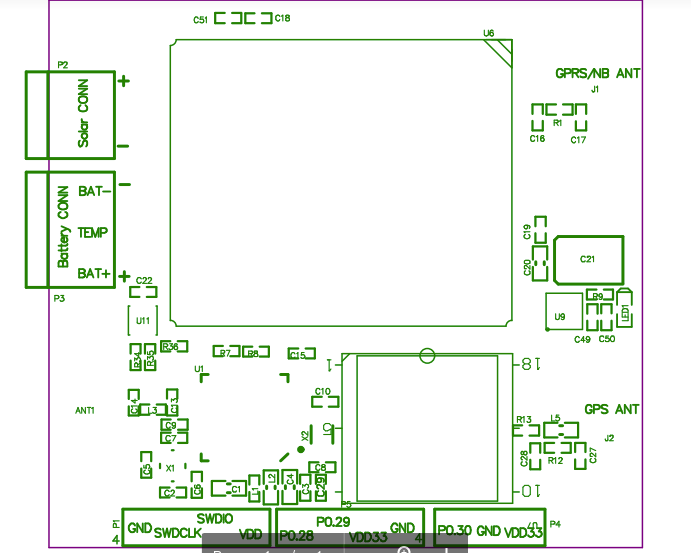
For this try and connect a ftdi chip to the itracker board. The rx of the ftdi usb board should connect to the TX of the itracker board. The iTracker pinout for TX is as shown below:
Pin P0.29 is the TX pin of the board that should connect to the RX pin on the ftdi chip. ALso make sure to connect the ground on the two board :)
Now fire up you favourite Terminal and point it to the port designated to the USB serial board at these setting
- baudrate - 9600
- Parity - NONE
- DATA Bits - 8
- Stop Bits - 1
And do the same change to the characteristics that we did above, enterin 00 or 01 as required and see the serial output in your app.
Sooo... your IDE is setup and you were able to run your very first sketch. NICEEE. in the next tutorial, we will see a bt more about the BLE protocol. How the GATT protocol works and how do we intercat with the various services ina BLE device.
Adafruit libraries:As a step up from the BLE PEripheral library, The adafruit libraries are also based on the sandeepmistry core and hence should work out of the box with the iTracker BLE board
The library and the examples are here:
https://github.com/adafruit/Adafruit_nRF52_Arduino
Under libraries is the lib files for use with the arduino IDE, examples will provide examples for the Adafruit core.
MEGA Update: Support for Sparkfun Arduino core and serial/DFU bootloaders:
I have been working on supporting Serial as well as DFU OTA bootloaders on the itracker module and i have been able to achieve the same. you can visit the Repo below:
https://github.com/narioinc/iTracker-ArduinoIDE
It has all the instruction to get your itracker working with the arduino IDE and also use the serial bootloader if need be.
Some pre-requisites to using the serial bootloader.
1) you need the itracker usb to serial base adapter board.
2) you need to edit the Arduino IDE Sparkfun core with the board variant files I have provided in the repo above
Thanks to the awesome guys at sparkfun and sandeep mistry for their work on the arduino core for nrf52


_M6kErcYJ84.png?auto=compress%2Cformat&w=40&h=40&fit=fillmax&bg=fff&dpr=2)


_3u05Tpwasz.png?auto=compress%2Cformat&w=40&h=40&fit=fillmax&bg=fff&dpr=2)
Comments
Please log in or sign up to comment.