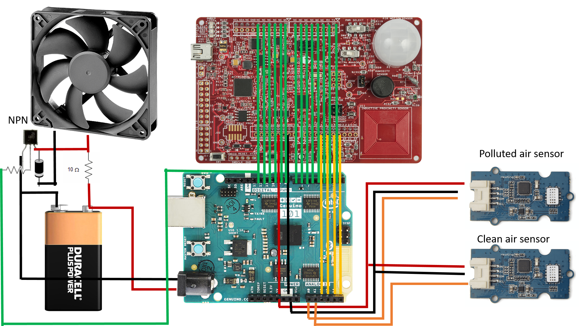
#include <Wire.h> // Wire library that helps the Arduino with i2c
#include <Streaming.h> // Streaming C++-style Output with Operator << from http://arduiniana.org/libraries/streaming/

//------------------------------------------------------------------------------
// CONFIGURATION
//------------------------------------------------------------------------------

// define FAST sensor sampling interval
unsigned long INTERVAL_FAST = 5000; // sample duration (ms)30s, david holstius used 60000
unsigned long last_time_fast_ms;     // time of last check/output

String s3 = "C12=";
String s = "";
String si2="";
String sd="SF";
//int x=0;

char inChar;
int i1 = 0;
int i2 = 0;
int OK = 0;
int SIGNAL = 0;

//int reset;
//int w;
int sdc=0;
//int r=0;


//------------------------------------------------------------------------------
// COMPONENT SETUP
//------------------------------------------------------------------------------

//-------------------------------------------------------------------------- MUX

int MUX_BASE = 0; // analog pin to interact with mux
int MUX_CONTROL[] = {
  2, 3, 4, 5}; // digital pins for mux pin selection
int mux(int channel) {
  // select channel on multiplexer
  for (int i = 0; i < 4; i++) {
    digitalWrite(MUX_CONTROL[i], bitRead(channel, i));
  }
  // return base pin for analogRead/Write to use
  return(MUX_BASE);
}

void setup_mux() {
  // set digital pins controlling multiplexer to OUTPUT
  for (int i = 0; i < 4; i++) {
    pinMode(MUX_CONTROL[i], OUTPUT);
  }
}

//------------------------------------------------------------ SD card (logging)

#include "SD.h" //SD library to talk to the card
#define SD_PIN 10 // for the data logging shield, we use digital pin 10 for the SD cs line
#define SD_INTERVAL_SYNC 1000 // mills between calls to flush() - to write data to the card
uint32_t sd_last_time = 0; // time of last sync()
File logfile; // the logging file

// setup
void setup_sd() {
  //digitalWrite(SD_PIN, HIGH);
  pinMode(SD_PIN, OUTPUT); // default chip select pin is set to output

  if (!SD.begin(SD_PIN)) { // see if the card is present and can be initialized
    sdc=1;
    return; // don't do anything else
  }
  // create a new file, LOGGERnnnn.csv (nnnn is a number), make a new file every time the Arduino starts up
  char filename[] = "0000.csv";
  for (uint16_t i = 0; i < 10000; i++) {

    for (int j = 0; j < 4; j++) {
      filename[4-j-1] = ((int)(i / pow(10, j)) % 10) + '0';
    }

    if(!SD.exists(filename)) { // only open a new file if it doesn't exist
      logfile = SD.open(filename, FILE_WRITE); // Unix style command flags - logfile.open() procedure FILE_WRITE - create the file and write data to it
      break;  // leave the loop!
    }
  }
  if (!logfile) {
    //logfile<<"could not create file"<<endl;
    sdc=1;
  }
  sd_last_time = millis();
}

// --------------------------------------------------- GPRS setup

void setupIP()
{
  SIGNAL=0;
  i1=0;
  while (SIGNAL==0) {
    delay(10000);
    logger();
    for (int i=0; i<5; i++)
    {
      Serial.println("AT+CGATT?"); //this command is used to attach/detach from GPRS service. the ? should say if you are physically connected i think
      delay(2000);
      ShowSerialData();
    }
    logger();

    if (i1==0) {
      Serial.println("AT+CPOWD=1"); //power off the module
      delay(5000);
      SIM900power();
    }
  }

  Serial.println("AT+CIPSHUT"); //reset the ip session if any
  delay(2000);

//  Serial.println("AT+CIPSTATUS"); //check if the ip stack is initialized
//  delay(2000);

  Serial.println("AT+CIPMUX=0"); //this is to set the connection mode to single i.e 0
  delay(2000);

  Serial.println("AT+CSTT=\"internet.com\",\"wapuser1\",\"wap\""); //start task and set APN, APN is the access point name which interfaces 3G with the internet
  delay(1000);

  Serial.println("AT+CIICR"); //bring up wireless connnection with GPRS
  delay(3000);

  Serial.println("AT+CIFSR"); //get local IP address
  delay(2000);

  Serial.println("AT+CIPSPRT=0"); //set prompt of > when sending data
  delay(3000);

  Serial.println("AT+CIPSTART=\"tcp\",\"m2.exosite.com\",\"80\""); //start up TCP connection
  delay(3000);

}


//------------------------------------------------------ Chronodot (timekeeping)

#include "Chronodot.h" // Chronodot RTC library
Chronodot RTC;

// setup
void setup_rtc() {
  // kick off the RTC initializing the Wire library - poking the RTC to see if its alive
  Wire.begin();
  RTC.begin(); // Chronodot
}

void log_time2() {
  DateTime now = RTC.now();
  int year  = now.year();
  int month = now.month();
  int day   = now.day();
  int hours = now.hour();
  int mins  = now.minute();
  int secs  = now.second();
  logfile << "\"" << year;
  logfile << "-" << ((month<10)?"0":"") << month;
  logfile << "-" << ((day<10)?"0":"")   << day;
  logfile << " " << ((hours<10)?"0":"") << hours;
  logfile << ":" << ((mins<10)?"0":"")  << mins;
  logfile << ":" << ((secs<10)?"0":"")  << secs;
  logfile << "\",";
}

//---------------------------------------------------------- DHT22 (temperature)

#include "DHT.h"
#define DHT_PIN 7
#define DHT_TYPE DHT22   // DHT 22  (AM2302)
DHT dht(DHT_PIN, DHT_TYPE);

// setup
void setup_dht() {
  dht.begin();
}

// log
void log_dht() {
  // Reading temperature or humidity takes about 250 milliseconds!
  // Sensor readings may also be up to 2 seconds 'old' (its a very slow sensor)
  int h = dht.readHumidity();
  int t = dht.readTemperature();
  // check if returns are valid, if they are NaN (not a number) then something went wrong!
  if (isnan(t) || isnan(h)) {
    //    log_error("DHT22", "failed to read");
  }
  else {
    logfile<<h<<",";
    logfile<<t<<",";

  }
  s+=String(h)+",";
  s+=String(t)+",";
}

//----------------------------------------------------------- Sinyei (particles)

#define SNY_PIN 8
unsigned long sny_duration;
unsigned long sny_lowocc_us = 0; // sum of time spent LOW

unsigned long SNY_INTERVAL_ms = 30000; // sample duration (ms)30s, david holstius used 60000
unsigned long sny_last_time;           // time of last serial dump

// setup
void setup_sinyei() {
  pinMode(SNY_PIN, INPUT);
  sny_last_time = millis();
  sny_lowocc_us = 0;
}

// reading
void log_sinyei(unsigned long lowocc_us, unsigned long sampletime_ms) {
  float ratio;
  ratio = lowocc_us / (sampletime_ms * 1000.0) * 100.0;
  logfile<<ratio<<",";

  si2=String(ratio);
}

//------------------------------------------------------------ Sharp (particles)

// connected to analog 1 and controlled by digital 9
#define SRP_PIN_DUST 1
#define SRP_PIN_LED 9 // led Power is any digital pin on the arduino connected to Pin 3 on the sensor (can be 2, 4,)

int srp_delay1_us = 280; // delays are in microseconds
int srp_delay2_us = 40;
int srp_delayoff_us = 9680;

// setup
void setup_sharp() {
  pinMode(SRP_PIN_LED, OUTPUT);
}

// log
void log_sharp() {
  digitalWrite(SRP_PIN_LED, LOW); // power on the LED
  delayMicroseconds(srp_delay1_us);
  int dustVal = analogRead(SRP_PIN_DUST); // read the dust value
  delayMicroseconds(srp_delay2_us);
  digitalWrite(SRP_PIN_LED, HIGH); // turn the LED off
  delayMicroseconds(srp_delayoff_us);
//
  logfile<<dustVal<<",";
  s+=String(dustVal);
}

// ------------------------------------------------------- voltage

long read_vcc() {
  // Read 1.1V reference against AVcc
  // set the reference to Vcc and the measurement to the internal 1.1V reference
#if defined(__AVR_ATmega32U4__) || defined(__AVR_ATmega1280__) || defined(__AVR_ATmega2560__)
  ADMUX = _BV(REFS0) | _BV(MUX4) | _BV(MUX3) | _BV(MUX2) | _BV(MUX1);
#elif defined (__AVR_ATtiny24__) || defined(__AVR_ATtiny44__) || defined(__AVR_ATtiny84__)
  ADMUX = _BV(MUX5) | _BV(MUX0);
#elif defined (__AVR_ATtiny25__) || defined(__AVR_ATtiny45__) || defined(__AVR_ATtiny85__)
  ADMUX = _BV(MUX3) | _BV(MUX2);
#else
  ADMUX = _BV(REFS0) | _BV(MUX3) | _BV(MUX2) | _BV(MUX1);
#endif
  delay(2); // Wait for Vref to settle
  ADCSRA |= _BV(ADSC); // Start conversion
  while (bit_is_set(ADCSRA,ADSC)); // measuring
  uint8_t low  = ADCL; // must read ADCL first - it then locks ADCH
  uint8_t high = ADCH; // unlocks both
  long result = (high<<8) | low;
  result = 1125300L / result; // Calculate Vcc (in mV); 1125300 = 1.1*1023*1000
  return result; // Vcc in millivolts
}

//------------------------------------------------------- Other GPRS functions


void SIM900power()
// software equivalent of pressing the GSM shield "power" button
{
  pinMode (6,OUTPUT);
  digitalWrite(6,LOW);
  delay(1000);
  digitalWrite(6, HIGH);
  delay(2000);
  digitalWrite(6, LOW);
  delay(3000);
}


void TCPDisconnect()
{
  Serial.println("AT+CIPCLOSE"); //close the TCP connection
  delay(5000);
  //ShowSerialData();
}

//------------------------------------------------------------------------------
// SETUP
//------------------------------------------------------------------------------

void(* resetFunc) (void) =0;

void setup(void) {

  SIM900power();
  // setup serial
  Serial.begin(19200);
  setupIP();
  //TCPConnect();

  setup_rtc(); // all logging depends on RTC, so start it up first
  setup_sd();
  setup_mux();
  setup_dht();
  setup_sinyei();
  setup_sharp();

  // set fast sensor clock
  last_time_fast_ms = millis(); // get the current time

  s = s3;

}

//------------------------------------------------------------------------------
// MAIN LOOP
//------------------------------------------------------------------------------


void loop() {

  logger();

  s+=","+si2;
  if (sdc==1) {
    s+=","+sd;
    sdc=0;
  }

  si2="";
  sendtoExosite();
  s=s3;
  // reset clock to current time
  last_time_fast_ms = millis();

  //--------------------------------------------------------------- sync SD card

  // write data to disk! Don't sync too often (2048 bytes of I/O SD card, a lot of power, takes time)
  if ((millis() - sd_last_time) > SD_INTERVAL_SYNC) {
    logfile.flush();
    sd_last_time = millis();
  }

}

void logger() {

  sny_duration = pulseIn(SNY_PIN, LOW);
  sny_lowocc_us += sny_duration;

  //-------------------------------------- read/lMog Sinyei sensor (30s interval)

  if ((millis() - sny_last_time) > SNY_INTERVAL_ms) {

    // log Sinyei
    log_sinyei(sny_lowocc_us, millis() - sny_last_time);

    // reset
    sny_lowocc_us = 0;
    sny_last_time = millis();
  }

  logfile<<endl;

  log_time2();
  log_dht();
  log_sharp();

  int num_sensors = 16;
  int sensor_value;

  for (int channel = 0; channel < num_sensors; channel++) {
    sensor_value = analogRead(mux(channel));
    if (channel==0 || channel==1 || channel==2 || channel==4 || channel==5 || channel==6 || channel==7 || channel==9 || channel==10 || channel==11){
      logfile<<sensor_value<<",";
      s+=",";
      s+=String(sensor_value);
    }
  }
  delay(100);

}

void sendtoExosite()
{

  int num;
  String le;
  num=s.length();

  le=String(num);

  i1=0;
  i2=0;
  OK=0;

  Serial.println("AT+CIPSEND"); //begin sending data to remote server
  delay(1700); //was 2000

  Serial.flush();
  ShowSerialData(); // i definitely need to read this response since it will let me know whether the data was sent or not

  Serial.println("POST /onep:v1/stack/alias HTTP/1.1");
  delay(50);

  Serial.println("Host: m2.exosite.com");
  delay(50);

  Serial.println("X-Exosite-CIK: 1e6012249cd51557a55b6ec8305543a53ec93d83");
  delay(50);

  Serial.println("Accept: application/x-www-form-urlencoded; charset=utf-8");
  delay(50);

  Serial.println("Content-Length: "+le);
  delay(50);

  Serial.println("Content-Type: application/x-www-form-urlencoded");
  delay(50);

  Serial.println("");
  delay(50);

  Serial.println(s); //this is where the data I want to send goes
  delay(50);

  Serial.flush();
  delay(500); //was 600
  ShowSerialData();

  Serial.println((char)26);
  delay(2500); //was 2700

  /*
  This part of the code is to troubleshoot if the data is not sending
  */

  if (OK==0) //if the response did not read 'OK' then that means that the data did not send and is probably not connected so I have to reconnect
  {
    Serial.println("NOT WORKING");
    TCPDisconnect();
    setupIP();
    //TCPConnect();
  }
}

void ShowSerialData() // this is where I view the response and index OK if I am using software serial or just index OK if i am using hardware serial
{
  while(Serial.available()!=0)
  {
    inChar = Serial.read();
    if (inChar=='1') {
      SIGNAL++;
    }
    if (inChar=='O') {
      i2=i1;
    }
    if (inChar=='K' && i1-i2==1) {
      OK++;
    }
    i1++;
  }
}


_baVEVgguW1.jpg?auto=compress%2Cformat&w=48&h=48&fit=fill&bg=ffffff)


Comments
Please log in or sign up to comment.