

Hardware components | ||||||
 |
| × | 1 | |||
Hand tools and fabrication machines | ||||||
 |
| |||||
 |
| |||||
In this clip the Chernobyl Dice set to continuously generate numbers in the range [1, 26]. You can check out a longer YouTube clip showing various modes of here: https://youtu.be/8uue9Aae9ss
IntroductionDescription
The Chernobyl Dice is a quantum random number generator [0] that uses nuclear decays from a weakly radioactive sample as a source of entropy. You can view the GitHub repository and all the files necessary for construction here:
https://github.com/nategri/chernobyl_dice
It consists of four primary components:
- An Arduino Nano microcontroller
- A Geiger counter
- Six uranium glass marbles
- Nixie tube display
Geiger counter events ("clicks") are converted into random bits using the following algorithm:
1. In a ring buffer, for each millisecond record either a 0 or a 1, depending on whether or not a Geiger event occurred
2. Perform an initial de-bias of this 0-dominated stream using von Neumann's method [0]
3. Further de-bias by XOR-ing bits generated in the previous step with the mod2 of elapsed 4 microsecond intervals since since the device was powered on
The uranium glass sample is illuminated by an array of ultraviolet LEDs at each Geiger event, which makes them fluoresce bright green. This has nothing to do with the radioactivity of the sample, but it does, however, look really cool.
Operation
The device has three modes of operations, which can be selected via the rotary switch:
Clock Mode
Displays the current time, with the Geiger board unpowered. The time can be set by flipping the toggle switches on and off(the '16' toggle increments the hour, the '8' toggle increments 10 minutes, the '4' toggle increments 1 minute, and the'1' toggle resets the seconds).
Streaming Mode
Repeatedly generates random numbers of a size specified by the toggles (or random bytes from 0-255 if no toggles are set). Numbers generated in this mode are transmitted over serial via USB. This mode also has a "turbo" setting to facilitate statistical testing, which can be enabled by holding down the pushbutton. When "turbo" is enabled bit generation will be indicated by LEDs in the display, and the Geiger "clicks" will be silent.
Dice Mode
In dice mode random number generation is initiated via the pushbutton, and the size of the random number to be generated is set by the sum of the toggled switches (no switches are set the device will generate random byte in the range 0-255). Press once to generate the number, and once again to clear the display. The size of the number to be generated is displayed in blinking digits.
Statistical PerformanceFurther testing is required to confirm the consistency of results, but currently the Chernobyl Dice is capable of generating a 1.5+ megabit file that passes a Python implementation of the NIST statistical test suite [1]. This means the Chernolbyl Dice is likely a very fair dice.
SUMMARY
-------
monobit_test  0.279698915238  PASS
frequency_within_block_test 0.404035783453  PASS
runs_test 0.0688862287393 PASS
longest_run_ones_in_a_block_test  0.959135200804  PASS
binary_matrix_rank_test 0.532456847429  PASS
dft_test  0.000155432528185 FAIL
non_overlapping_template_matching_test  0.999998184707  PASS
overlapping_template_matching_test  0.55898054206 PASS
maurers_universal_test  0.224223569722  PASS
linear_complexity_test  0.672504584189  PASS
serial_test 0.424389760139  PASS
approximate_entropy_test  0.425255814114  PASS
cumulative_sums_test  0.348500456103  PASS
random_excursion_test 0.0753308212732 PASS
random_excursion_variant_test 0.207160448911  PASS


SUMMARY
-------
monobit_test  0.105735760191  PASS
frequency_within_block_test 0.436487225319  PASS
runs_test 0.648059641506  PASS
longest_run_ones_in_a_block_test  0.184787158208  PASS
binary_matrix_rank_test 0.310400523277  PASS
dft_test  0.156504142574  PASS
non_overlapping_template_matching_test  1.00000015958 PASS
overlapping_template_matching_test  0.629208901365  PASS
maurers_universal_test  0.938296605093  PASS
linear_complexity_test  0.0880093291441 PASS
serial_test 0.131826155057  PASS
approximate_entropy_test  0.137234909215  PASS
cumulative_sums_test  0.112328349057  PASS
random_excursion_test 0.17207234069 PASS
random_excursion_variant_test 0.299605480729  PASS
Statistical test suite results for two 212667 byte random binary sequences ('rand.binary.1' and 'rand.binary.2') generated by device. EXPERTS NOTE: The last two tests of the first sequence generate the message: 'J too small (J=181 < 500) for result to be reliable' so these tests may be ignored for that dataset.
The directory statistical_testing contains some utilities for assessing and gathering data from the device, including sample random binary data files, rand.binary.1 and rand.binary.2.
A Fusion 360 CAD drawing of the device can be viewed and downloaded at this URL:
Thanks to the following GrabCAD users for their models:
- Alex (Nixie tube)
- Mike Smith (Arduino Nano)
- Dragos Ionescu (Various pin headers)
WARNING: These instructions and resources are not polished and are somewhat untested. This is a project for advanced makers, and you should fully expect to have a bit of an adventure while building your own Chernobyl Dice! That said: Shoot me a message if you run into trouble, and I'll try to help you out and improve the instructions as well.
Here's a rough outline of the steps required for assembly:
1. Print or fabricate the following custom parts from files in the GitHub repository
- Enclosure (using 3D printer or 3D printing service)
- Logic, Nixie Display, and Control Panel Custom PCBs (using a board fabrication service such as OSHPark)
- Stainless steel front panel (using a service such as OSHCut)
- Acrylic back panel (using a service such as Sculpeo)
2. Order other components (see URLs in the parts list)
3. Embed brass standoffs into enclosure (this is how front and back panels and custom PCBs will be mounted)
TIPS
- A single drop of cyanocrylate (superglue) should be placed in the standoff holes in the enclosure before they are pressed in (the tip of a Phillips head screw driver works well for this task)
- If the tops some holes came out of the printer a bit distorted then they can be widened easily by twisting a largish Phillips head screwdriver in them until the top of the hole is wide enough.
4. Assemble custom PCBs and 'exixe' nixie tube driver boards using build photos as a guide
TIPS
- The female headers on the Nixie Display Board for the nixie tube driver PCBs can be assembled using only four long female header strips (e.g. there's no need to separately attach sixteen 7-pin female headers---see photos)
- The "CS" 8-pin male header is a currently a tight fit, so you will probably need to use needle nose pliers to push the pins through the board
- For the control panel PCB you can temporarily mount the toggle switches in the front panel and then press the PCB on top of the back of the switches to ensure good alignment---you can then pull the whole board-and-toggle assembly off of the front panel to solder it, or even solder it in place and then pull it off
- The file 'nixie_holder.stl' is provided as a useful place to rest the nixie tube while soldering them to the 'exixe' driver boards
5. Attach the acrylic back panel and panel mount USB cable to the rear of the enclosure
6. Mount custom PCBs inside enclosure and perform wiring (see wiring schematic and build photos)
7. Partially dis-assemble rotary switch to attach it to the "lock plate" (lock_plate.stl)
8. Perform any necessary finishing to the stainless steel front panel
TIPS
- Some mounting holes for toggles and switches may need to be widened (use a round file for this)
- Surface finish of a laser cut part can be improved by sanding with the grain using ~300 grit sandpaper (test on the back side first)
9. Mount toggle-and-PCB assembly, LED-with-holder assemblies, rotary-switch-and-lock-plate assembly, and pushbutton on front panel
TIP
- While attaching the LED to the holder, apply a drop of cyanocrylate (superglue) to prevent the LED from falling out of the front of the holder
10. Perform wiring of the control panel (see wiring schematic and build photos)
11. Fit the eight nixie display driver boards into the female headers of the Nixie Display Board
12. Wire the Control Panel to the Logic Board
13. Mount the front panel to the enclosure, taking care to insure that the hole in the rotary switch lock plate lines up with the upper-left standoff on the front of the radioactive sample holder
Standoff Size Guide
NOTE: For large internal standoff distances (e.g. the Nixie Display mount) two standoffs can be stacked to achieve the desired distance.
Wiring DiagramHow connect the internal wiring of the Chernobyl Dice.
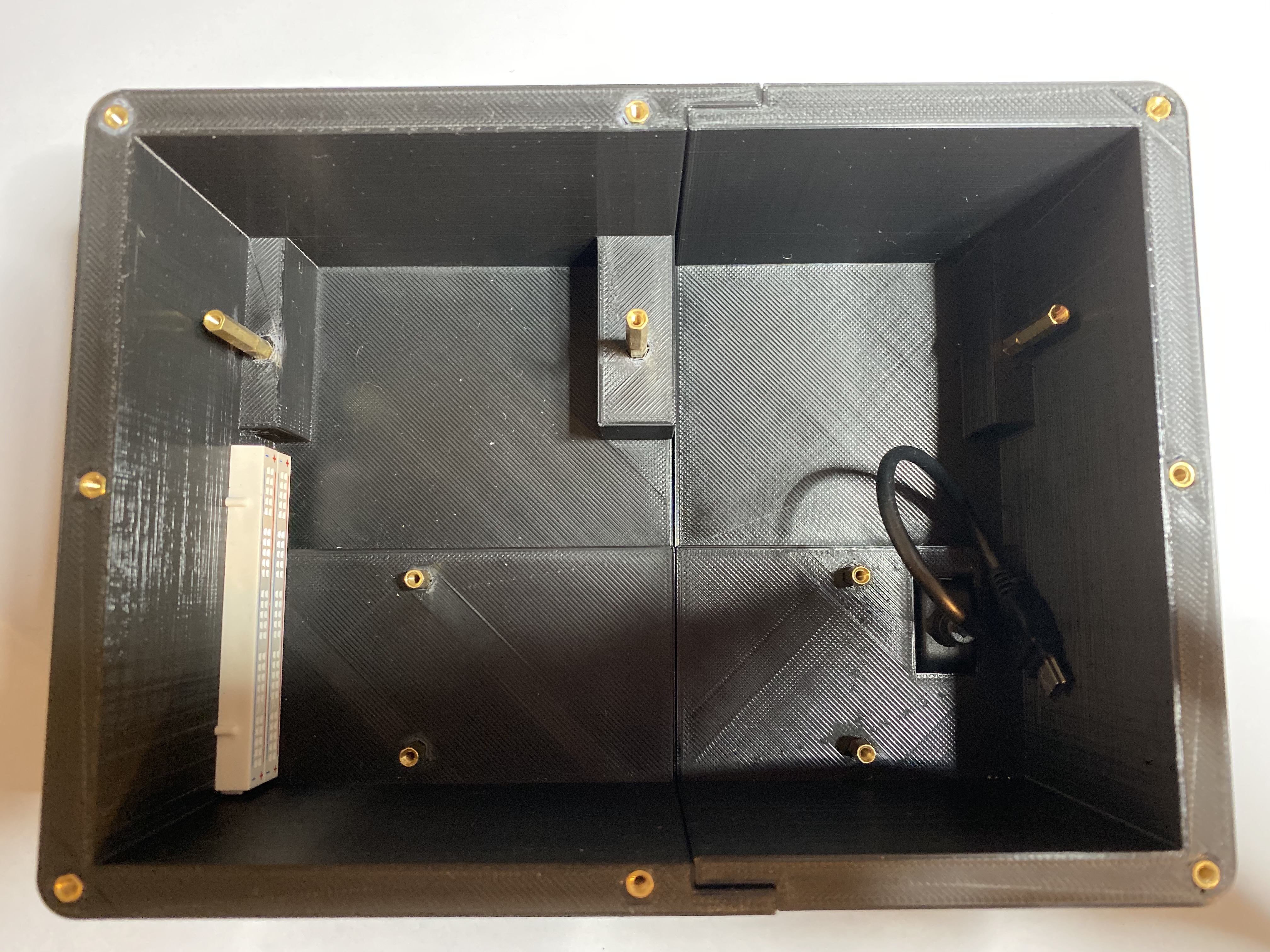
Build PhotosEnclosure with Standoffs Inserted
You can ignore the white breadboards on the left of the enclosure. These assisted in an earlier iteration of the project and are not needed for assembly. Click herefor larger photo.
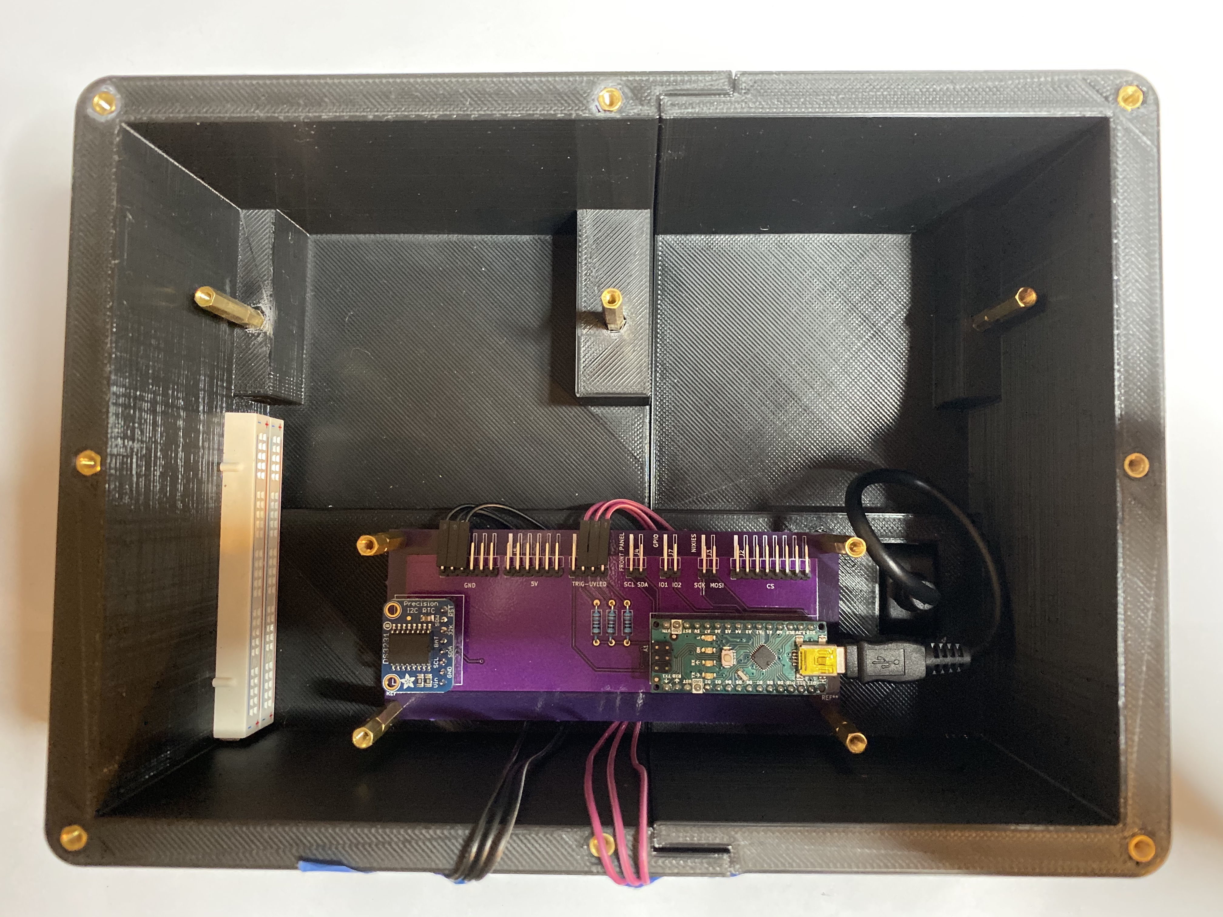
Logic Board Mounted
Note the wires for UV LED array are run beneath the logic board. Click herefor larger photo.
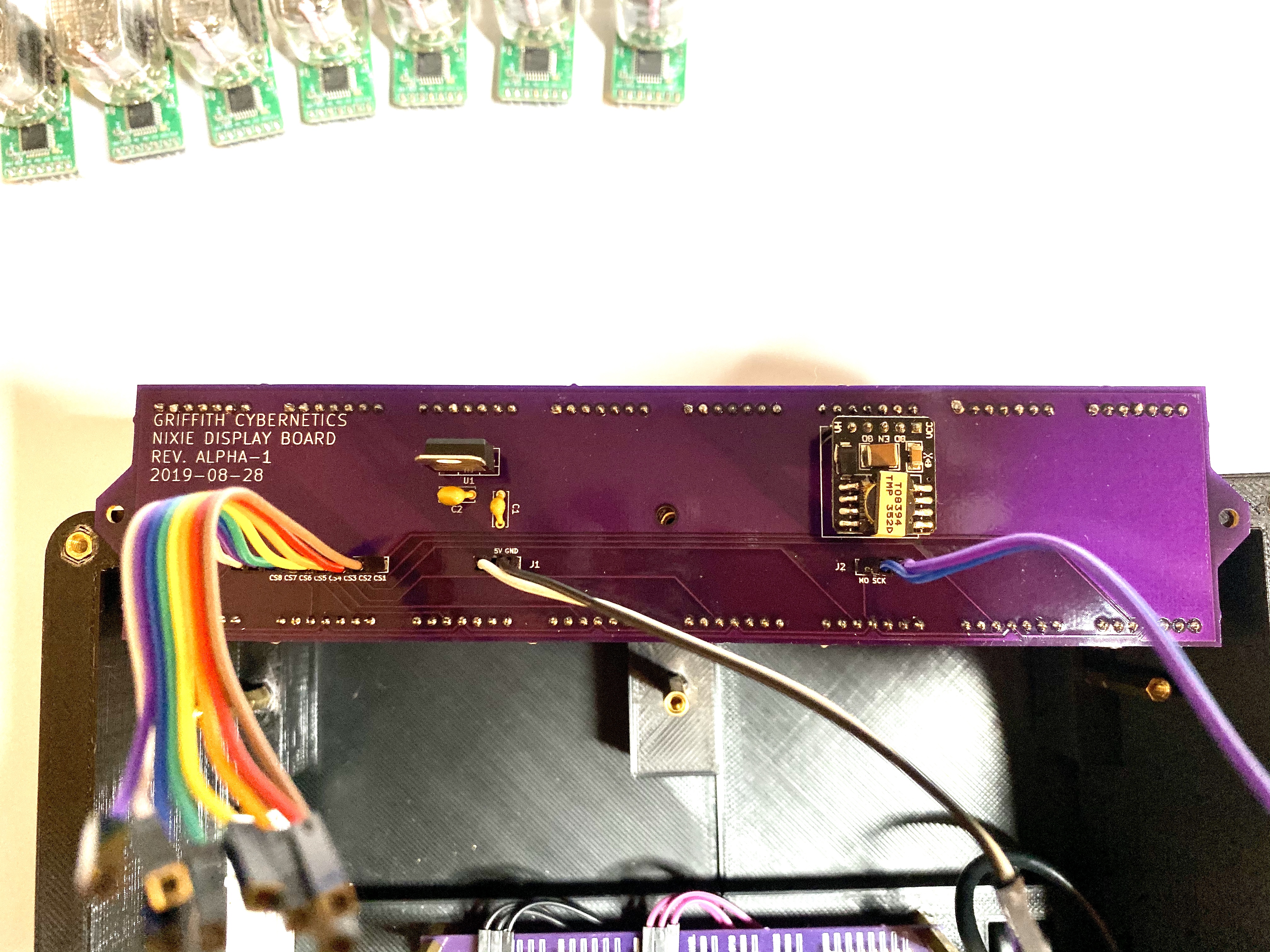
Nixie Display Board Wiring
Click herefor larger photo.
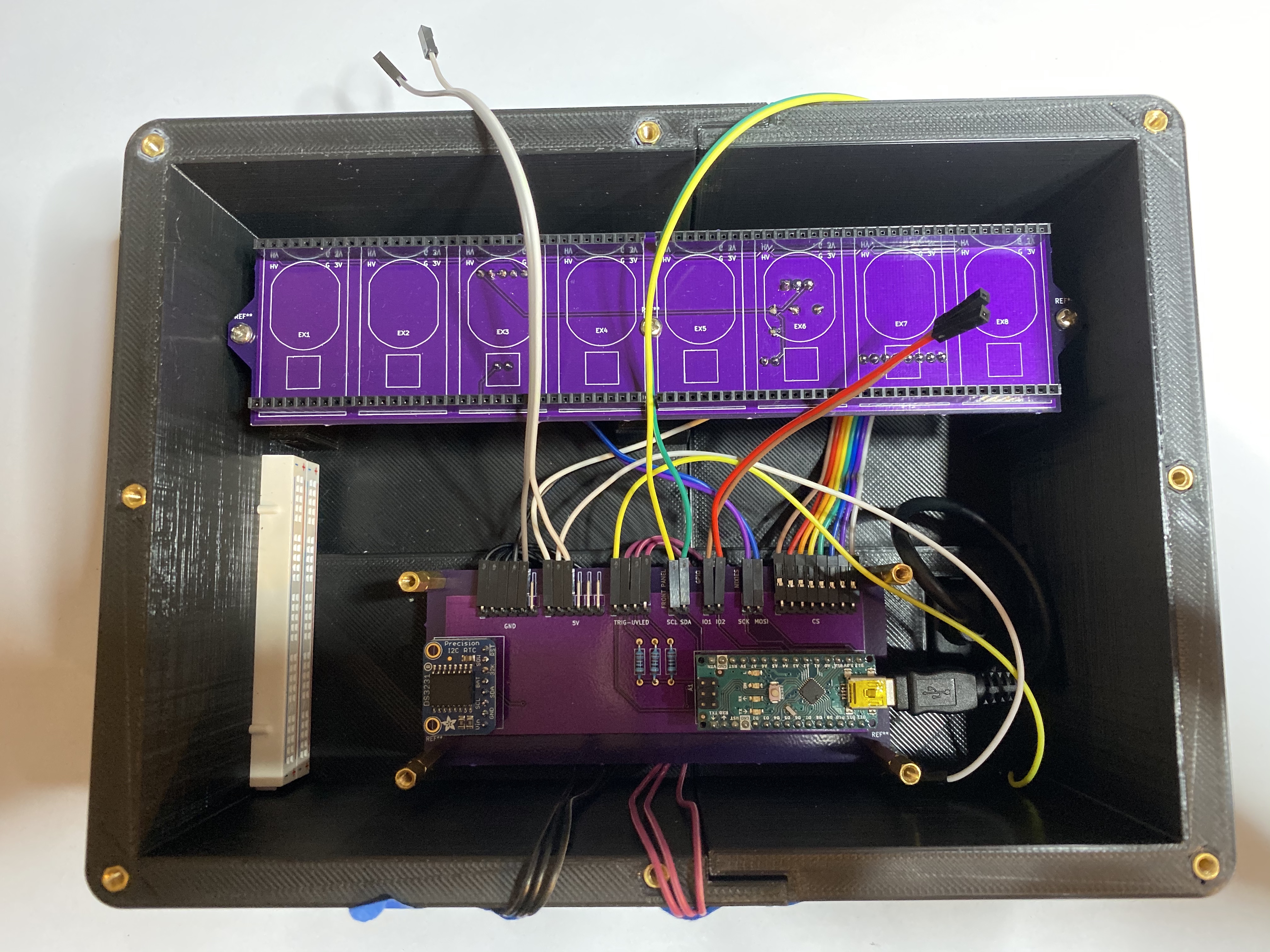
Nixie Display Board Mounted and Logic Board Wiring
Click herefor larger photo.
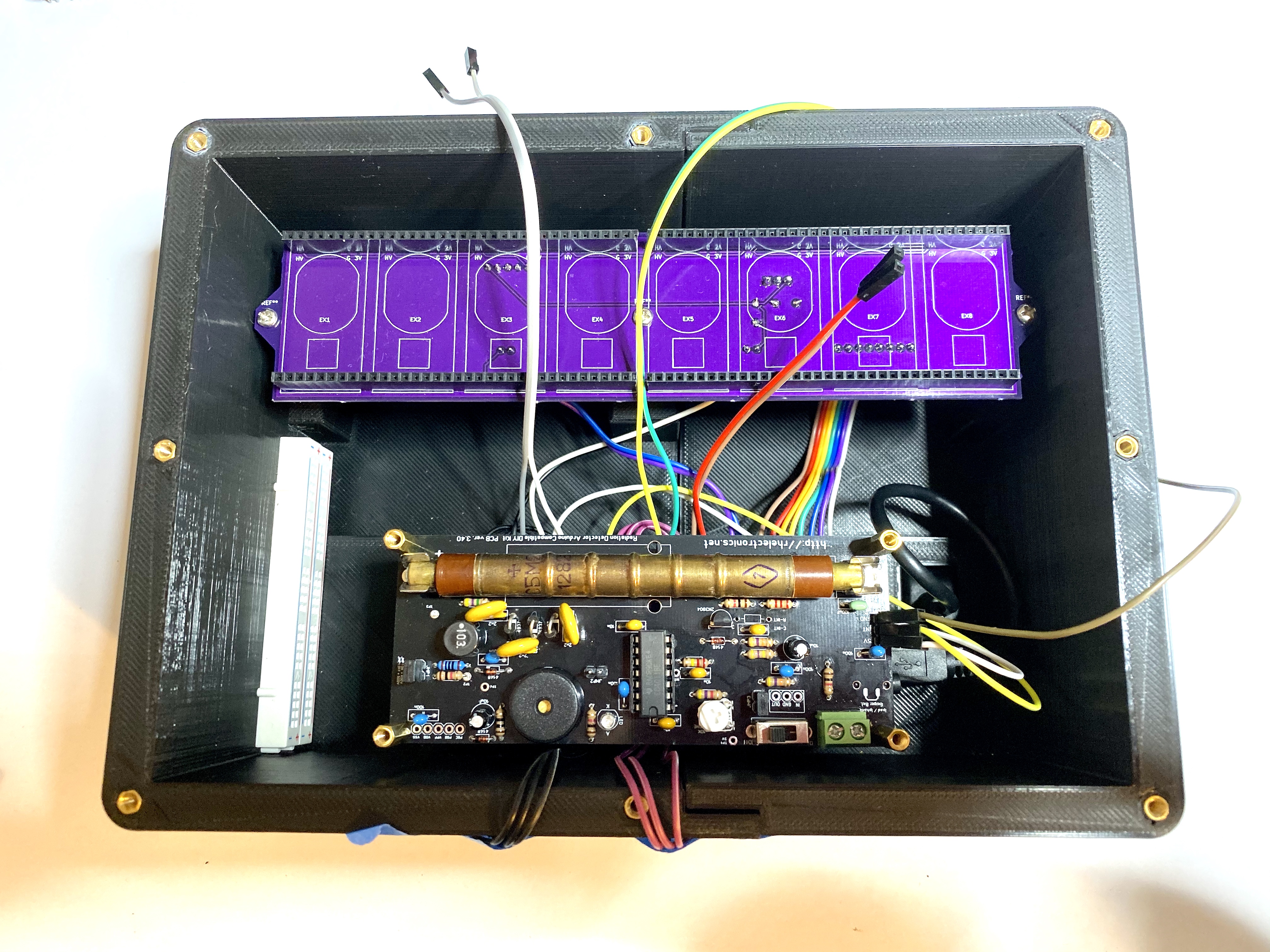
Geiger Board Mounted
NOTE: You must pull the JMP2 jumpber near the center of the Geiger board (this turns off the built-in speaker of the board---we want these clicks to be optional and controlled by firmware instead). Click herefor larger photo.
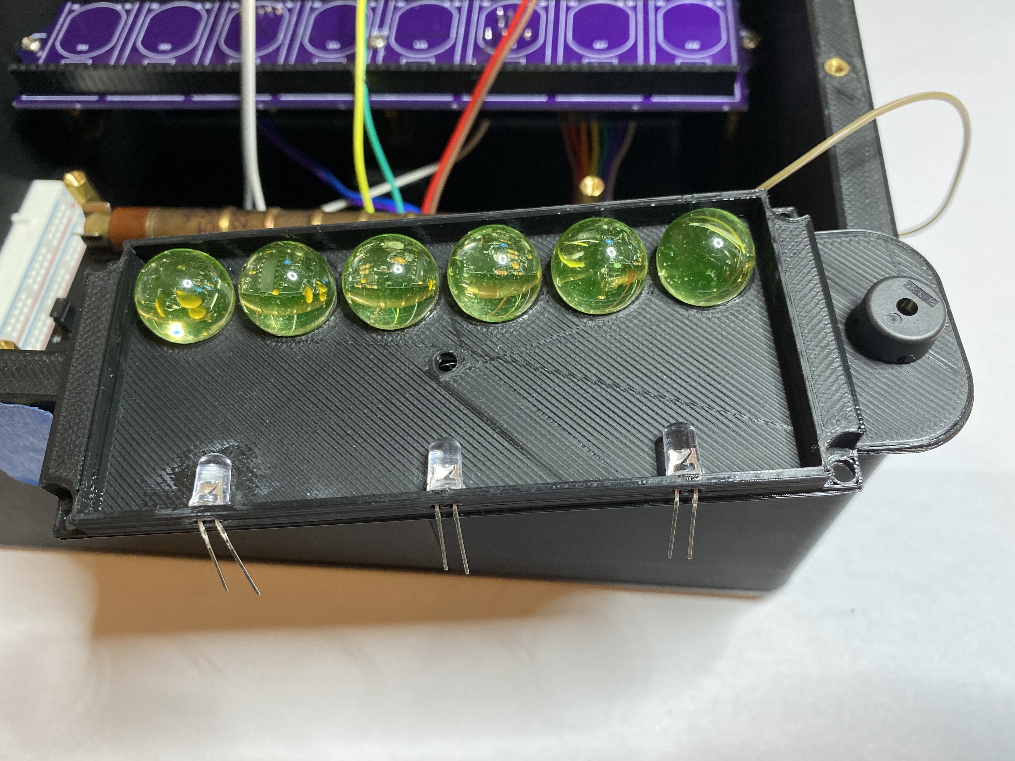
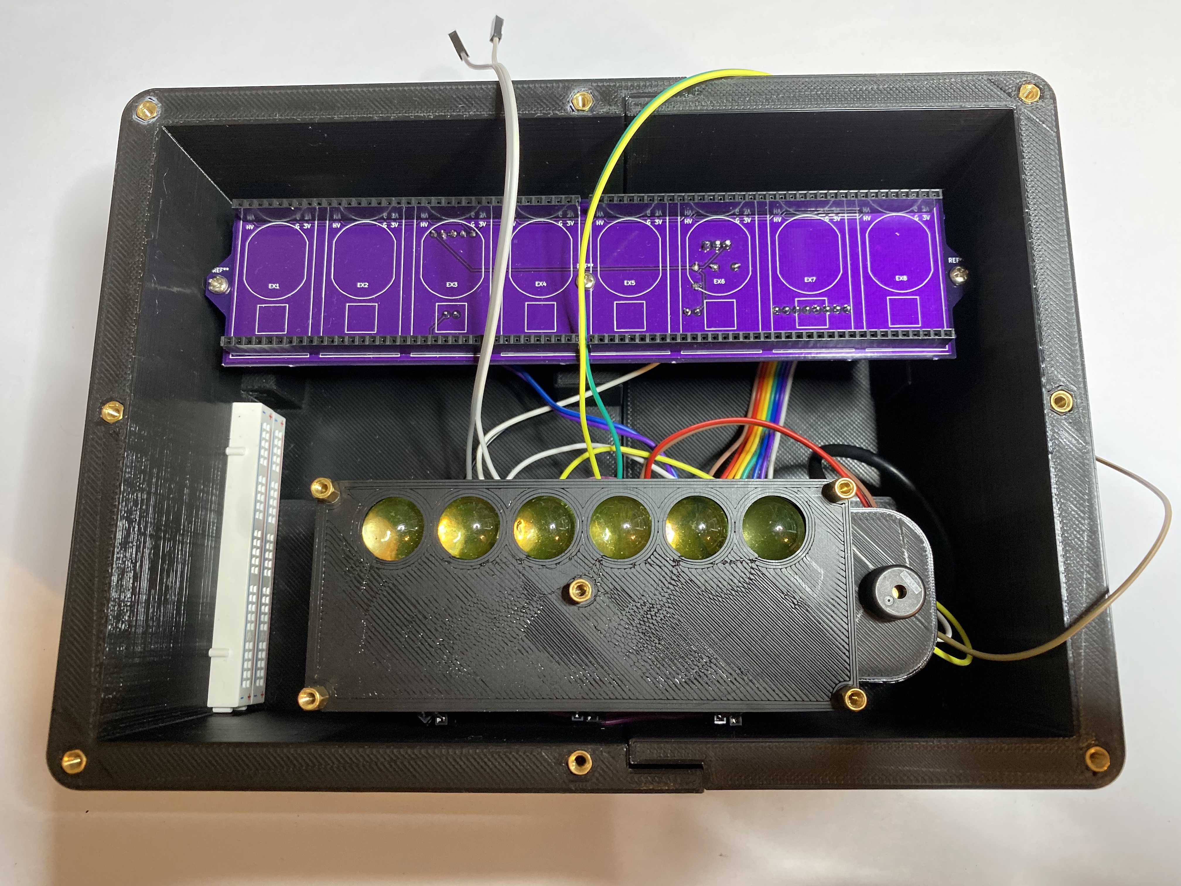
Uranium Sample Holder Lower Half Detail
UV LEDs and piezo speaker are glued mounted into place using cyanocrylate (superglue) adhesive. Uranium glass marbles will be held in place mechanically when the top half is mounted. Click herefor larger photo.
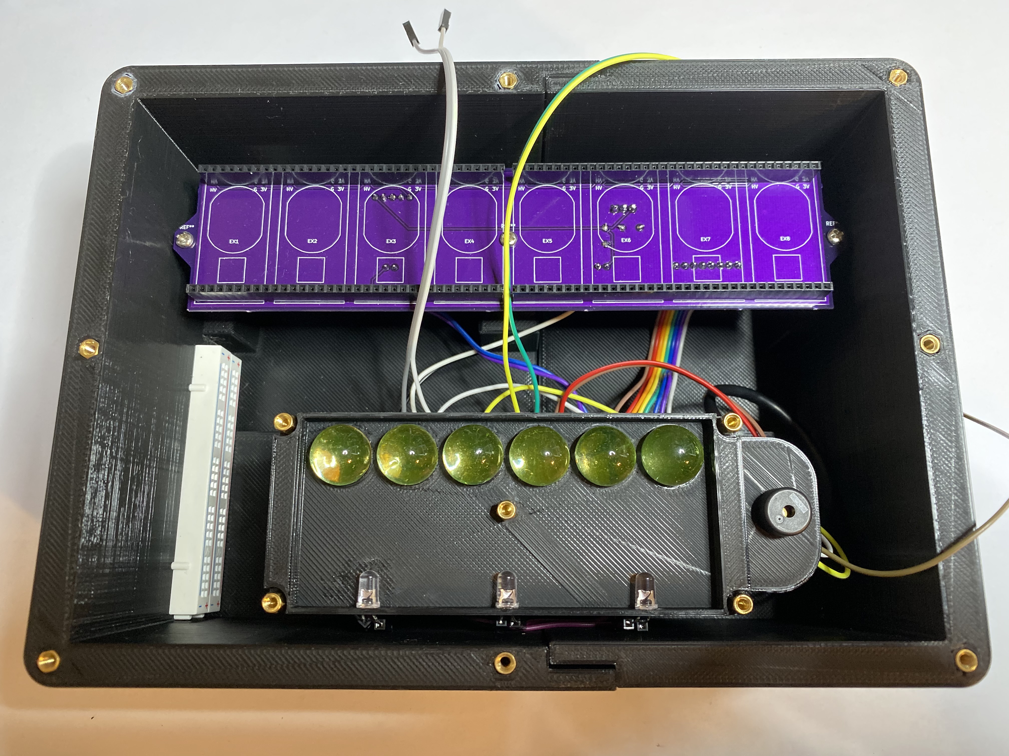
Uranium Sample Holder Lower Half Mounted
The middle standoff is attached on the underside with a nut. Click herefor larger photo.
Uranium Sample Holder Top Half Mounted
Click herefor larger photo.
Control Panel Board Wired
Click here for larger photo.
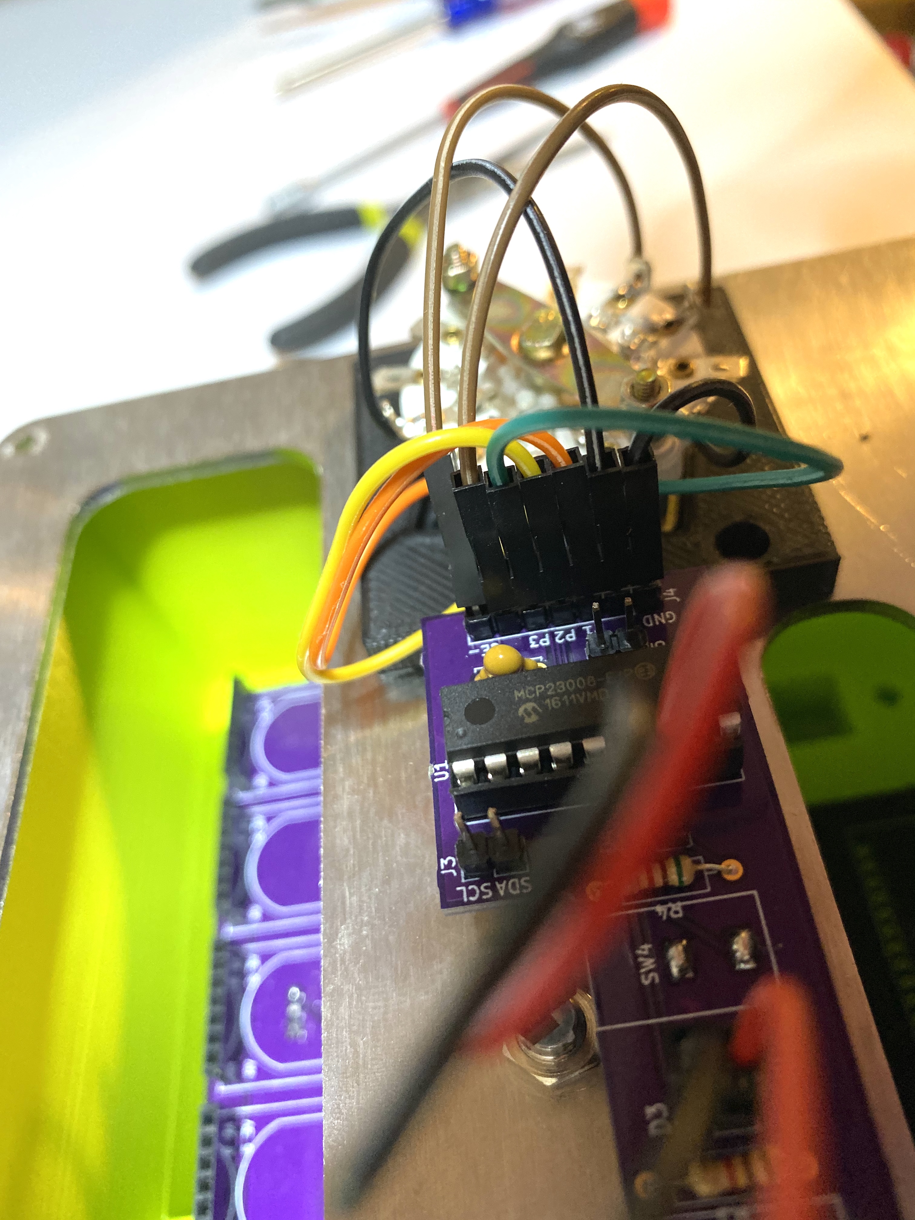
Control Panel Board Wiring Detail
Click herefor larger photo.
AcknowledgementsMany thanks to Emily Velasco (@MLE_Online) for advice on stainless steel surface sanding, and for generally being enthusiastic as heck about this project.
References[0] "Quantum Random Number Generators." M. Herrero-Collantes and J. C. Garcia-Escartin. https://arxiv.org/abs/1604.03304
[1] "A Statistical Test Suite for Random and Pseudorandom Number Generators for Cryptographic Applications." https://csrc.nist.gov/publications/detail/sp/800-22/rev-1a/final


Comments
Please log in or sign up to comment.