


Hardware components | ||||||
 |
| × | 1 | |||
_ztBMuBhMHo.jpg?auto=compress%2Cformat&w=48&h=48&fit=fill&bg=ffffff) |
| × | 1 | |||
_wzec989qrF.jpg?auto=compress%2Cformat&w=48&h=48&fit=fill&bg=ffffff) |
| × | 1 | |||
 |
| × | 1 | |||
 |
| × | 1 | |||
 |
| × | 1 | |||
| × | 1 | ||||
 |
| × | 10 | |||
 |
| × | 1 | |||
 |
| × | 1 | |||
 |
| × | 2 | |||
 |
| × | 2 | |||
| × | 1 | ||||
| × | 1 | ||||
Software apps and online services | ||||||
 |
| |||||
 |
| |||||
 |
| |||||
| ||||||
| ||||||
Hand tools and fabrication machines | ||||||
 |
| |||||
 |
| |||||
 |
| |||||
 |
| |||||
 |
| |||||
 |
| |||||
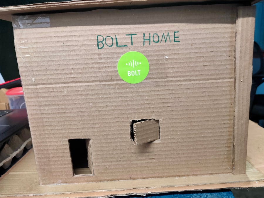
The main goal of this project is to protect our beautiful home from LPG gas leaking and fire accidents. Now we develop this alert system with the help of a bolt IoT module. This last part of this project I will demonstrate in a simple model house.
Becoming steps contains three words to simplify the long words
Arduino Mega – (AM)
Arduino UNO – (AU)
Sensors - (Sen)
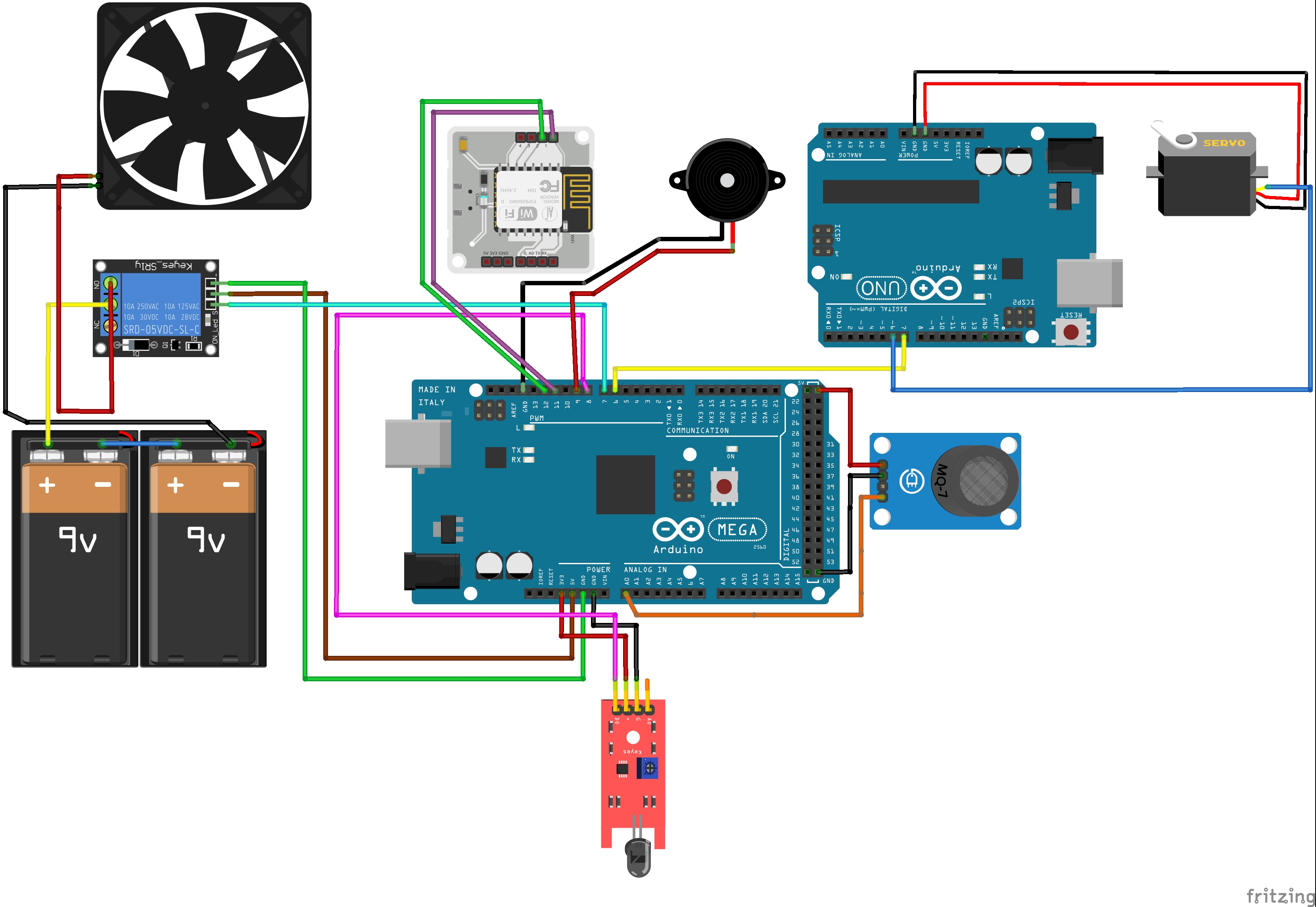
Connecting Components in Arduino mega boardStep 1Connect the flame sensor in Arduino mega digital pin and get the power source from Arduino mega.
PIN Configuration:AM 3.3 V ---------------------> Sen (VCC) +
AM GND ---------------------> Sen (GND) -
AM Digital pin 8 ------------> Sen (DO)
Step 2Connect the MQ-2 Gas sensor in Arduino mega digital pin and get the power source from Arduino mega.
PIN Configuration:AM 5 V ---------------------> Sen (VCC)+
AM GND ---------------------> Sen (GND) -
AM AO ------------> Sen (AO)
Step 3Connect the 5V Relay in Arduino mega digital pin and get the power source from Arduino mega.
PIN Configuration:AM 5 V ---------------------> Sen (VCC)+
AM GND ---------------------> Sen (GND) -
AM Digital pin 7 ------------> Sen (S)
Connect the Axial Fan wire, connect the axial fan Negative wire to 9v batteries negative terminal and connect a wire battery positive terminal to relays (COM) common point and next connect another wire from (NC) Normally closed to axial motors Negative wire.
Step 3Connect the “Bolt Module” in the Arduino mega digital pin and get the power source from the mobile charger via power cable.
PIN Configuration:AM Digital pin 11 ------------> bolt digital pin 1
AM Digital pin 12 ------------> bolt digital pin 2
Our Arduino mega components are successfully connected and the bolt module is also connected with the Arduino mega board.
Connecting Servo motor in Arduino UNO and Connect both Arduino boardsStep 1Connect the servo motor in the Arduino uno digital pin and get the power source from the Arduino board.
PIN Configuration:AU 5 V ---------------------> (VCC) +
AU GND ---------------------> (GND) -
AU Digital (PWM)pin 6 ------------> Signal
Step 2connect our both Arduino mega and Arduino uno boards using digital pins. The connection used to control the servo motor by Arduino MEGA with the help of an Arduino UNO board.
PIN Configuration:AM Digital pin 6 -------------> Digital pin 7 AU
Uploading codes to Arduino boards and writing codes in python codeStep 1Upload Arduino_mega_code to Arduino mega board and Arduino_UNO_code to arduino UNO board.
Step 2Write device api keys, ssid, device id and all credentials as safety_config file and send an alert message via sms and email by using python code.
Execute Our ProjectGive power to both Arduino and bolt IoT boards and then run the python code in VPS server.
First test runs our circuit, if the circuit can be implemented in a real world scenario. All of the workings and implementation are explained below the video.
SummaryFinally all circuit connection can perfectly works and sends alert message during any gas and fire can be detected in our home.


Comments
Please log in or sign up to comment.