M
Created November 29, 2023 © GPL3+

Swimmer Orientation with haptic feedback using ML

The device uses the angle of the lane lines relative to the swimmer adjusted with a gyroscope to provide haptic feedback to the swimmer.

Swimmer Orientation with haptic feedback using ML

Things used in this project

Hardware components

Blues Swan
Blues Swan
×1
UnitV2
M5Stack UnitV2
×1
tatoko DC Coreless Motor Built-in Vibration Waterproof 1.5-3v 8000-16000RPM Motor for Electric Toothbrush 7x25mm 5PCS
×1
Teyleten Robot GY-521 MPU-6050 MPU6050 3-Axis Accelerometer Gyroscope Sensor Module 6-axis Accelerometer Gyroscope Sensor Module IIC I2C 3-5V for Arduino 5pcs
×1

Software apps and online services

PlatformIO IDE
PlatformIO IDE
maixpy

Hand tools and fabrication machines

3D Printer (generic)

Story

Read more

Custom parts and enclosures

A Frame for the components

This frame is meant to seal the electronic components inside with a slot for the camera. Plenty of tape, laquer and other sealants should be used.

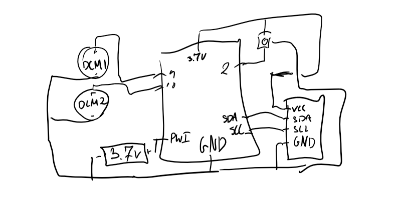
Schematics

Badly Drawn circuit Diagram

Code

Platform.io Swan board code

Python
Pull the serial output from the camera as well as the gyroscope to produce a more confident angle to orient the swimmer with by sending a haptic signal to the left and right vibrating motors. The severity of the angle is mapped to the intensity of the signal. There is also a trigger for calibration of gyroscope.
#include <Wire.h>
#include <Servo.h>
#include <MPU6050.h>

Servo leftMotor;
Servo rightMotor;

MPU6050 mpu;

float prevGyroAngle = 0.0;  // Previous gyroscope angle
float alpha = 0.98;         // Complementary filter constant

// Define gyro offset variables
float gyroXOffset = 0.0;
float gyroYOffset = 0.0;
float gyroZOffset = 0.0;

int calibrationButtonPin = 2;  // Pin to which the calibration button is connected
bool calibrateGyroFlag = false;

void setup() {
  Serial.begin(115200);

  leftMotor.attach(9);  // Connect left motor to pin 9
  rightMotor.attach(10); // Connect right motor to pin 10

  pinMode(calibrationButtonPin, INPUT_PULLUP);  // Set the button pin as input with pull-up resistor
  Wire.begin();
  mpu.initialize();

  if (!mpu.testConnection()) {
    Serial.println("MPU-6050 connection failed");
    while (1);
  }
}

void loop() {
  // Check if the calibration button is pressed
  if (digitalRead(calibrationButtonPin) == LOW) {
    calibrateGyroFlag = true;  // Set the flag to trigger gyroscope calibration
  }

  if (Serial.available() > 0) {
    // Read the orientation angle from the MaixPy Camera
    float cameraAngle = Serial.parseFloat();

    // Read gyroscope data
    float gyroAngle = readGyro();

    // Combine gyroscope and camera data using a complementary filter
    float combinedAngle = alpha * (prevGyroAngle + gyroAngle) + (1 - alpha) * cameraAngle;

    // Control the vibrational motors based on the combined angle
    controlMotors(combinedAngle);

    // Update the previous gyroscope angle for the next iteration
    prevGyroAngle = gyroAngle;
  }

  // Trigger gyroscope calibration if the flag is set
  if (calibrateGyroFlag) {
    calibrateGyro();
    calibrateGyroFlag = false;  // Reset the flag
  }
}

void calibrateGyro() {
  // Perform gyro calibration (adjust as needed)
  int numSamples = 1000;  // Adjust the number of samples as needed

  for (int i = 0; i < numSamples; i++) {
    int16_t gyroX, gyroY, gyroZ;
    mpu.getRotation(&gyroX, &gyroY, &gyroZ);

    // Accumulate gyro values for each axis
    gyroXOffset += gyroX;
    gyroYOffset += gyroY;
    gyroZOffset += gyroZ;

    delay(5);  // Adjust delay based on your specific requirements
  }

  // Calculate average offsets
  gyroXOffset /= numSamples;
  gyroYOffset /= numSamples;
  gyroZOffset /= numSamples;

  Serial.println("Gyroscope calibration completed!");
}

float readGyro() {
  // Read raw gyroscope data
  int16_t gyroX, gyroY, gyroZ;
  mpu.getRotation(&gyroX, &gyroY, &gyroZ);

  // Convert raw gyro values to degrees per second
  float gyroXrate = (gyroX - gyroXOffset) / 131.0;  // 131 LSB per degree/s
  float gyroYrate = (gyroY - gyroYOffset) / 131.0;
  float gyroZrate = (gyroZ - gyroZOffset) / 131.0;

  // Integrate gyro rates to get angle (simplified for demonstration purposes)
  float gyroAngleX = gyroXrate * 0.1;  // Integration with a simple time step
  float gyroAngleY = gyroYrate * 0.1;

  // Return the combined angle from the gyroscope (you may need to fine-tune this)
  return (gyroAngleX + gyroAngleY) / 2.0;
}

void controlMotors(float angle) {
  // Map the angle to motor speed (0 to 180)
  int motorSpeed = map(angle, -90, 90, 0, 180);

  // Adjust motor speeds based on the angle
  leftMotor.write(180 - motorSpeed);
  rightMotor.write(180 + motorSpeed);

  // Add a delay to avoid rapid changes (adjust as needed)
  delay(100);
}

MaixPy UnitV camera

MicroPython
Processes a live feed to detect lane lines and uses the strongest confidence to pull an angle to orient the device by.
import sensor
import image
import lcd
from machine import UART

# Initialize UART on MaixPy Camera
uart = UART(UART.UART1, baudrate=115200)

sensor.reset()
sensor.set_pixformat(sensor.RGB565)
sensor.set_framesize(sensor.QVGA)
sensor.run(1)

def detect_lane_lines(img):
    # Convert the image to grayscale
    img.to_grayscale()

    # Threshold the image to extract white lane lines
    img.binary([(200, 255)])

    # Use edge detection to enhance lane line features
    img.erode(1)
    img.dilate(1)

    # Find lines in the image
    img = img.find_lines(threshold=20, theta_margin=25, rho_margin=25, line_threshold=10, roi=(0, 180, 320, 60))

    if img:
        # Get the detected line
        lane_line = img[0]

        # Calculate the orientation angle of the lane line
        lane_line_angle = lane_line[1]

        # Send the lane line angle through serial communication
        uart.write("L" + str(lane_line_angle) + '\n')

        # Draw the lane line on the image
        img.draw_line(lane_line.line(), color=(0, 255, 0))

    return img

while True:
    img = sensor.snapshot()

    # Detect lane lines
    detect_lane_lines(img)

    # Display the image on the LCD
    lcd.display(img)

Credits

M

M

1 project • 0 followers

Comments