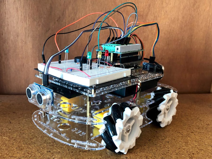
In this project I will be showing the process I used to build and control an omnidirectional car, utilizing mecanum wheels. The car will be controlled by a wireless PS2 controller and includes LEDs for speed indication, a small piezo horn, and HC-SR04 sensors for object detection.
The Chassis
The chassis that I used was sold as a set (EMOZY mecanum wheel robot kit) and purchased on amazon.
https://www.amazon.com/gp/product/B084TNLFYB/ref=ppx_yo_dt_b_asin_title_o02_s00?ie=UTF8&psc=1
This included:
- Four mecanum wheels
- Four DC motors with gear boxes
- two chassis plates
- standoffs
However it would be fairly easy to gather up the parts yourself, Adafruit sells very similar motors and gearboxes. https://www.adafruit.com/product/3777?gclid=CjwKCAjw3pWDBhB3EiwAV1c5rL1RGF34Q7nhI7VxfHFl_O1uBoj4WpKY2oM6noQD6oa1QQxTx2HJmxoCy1kQAvD_BwE
As well as the mecanum wheels https://www.adafruit.com/product/4678
Just make sure the wheels will work with the motors that you purchase. The chassis plates may be a little harder to come by. I bought a chassis plate for the top of the car from https://www.pololu.com/. They may have something that works.
AssemblyI would first recommend soldering the motor leads on if your motor does not come with them. It doesn't matter which lead goes where, just make sure the leads are long enough for your use case. If you are using the chassis kit it is fairly easy to assemble by following the directions. Just remember that the wheels need to go on a certain way, two of the wheels are for the right side and two for the left. This picture should help.
I also included an additional chassis plate purchased from pololu robotics (https://www.pololu.com/product/1545) to house the Arduino and breadboards. This is optional but the extra space was appreciated.
I mounted the top plate using M3 standoffs. This made room for the battery pack and the PS2 controller reciever.
Mountingthehardware
The hardware that I used includes:
- Arduino UNO
- Adafruit Motor Shield V2
- Electronics-Salon terminal shield
- Lynxmotion PS2 receiver breakout board.
- 6 X AA battery pack with barrel jack connector
- Two 400 point breadboards for LEDs and piezo
- On/off switch
I started by taping down the battery pack to the middle plate. It's important to make sure this doesn't move around too much when the car is moving. I also tapped down the on/off switch next to it. The PS2 breakout board was then mounted to the underside of the top plate. The Arduino Uno (along with the two shields) was this attached to the top plate using M2.5 standoffs. I also attached the two breadboards to the top plate. The HC-SR04 modules were attached to the front and back of the car using the mounting hardware that came with them. Conveniently the EMONZY chassis plates come with screw holes that match the HC-SR04 mounting brackets. There are many ways you could arrange all of these items on the car, probably many better ways than I did it, but it worked for me.
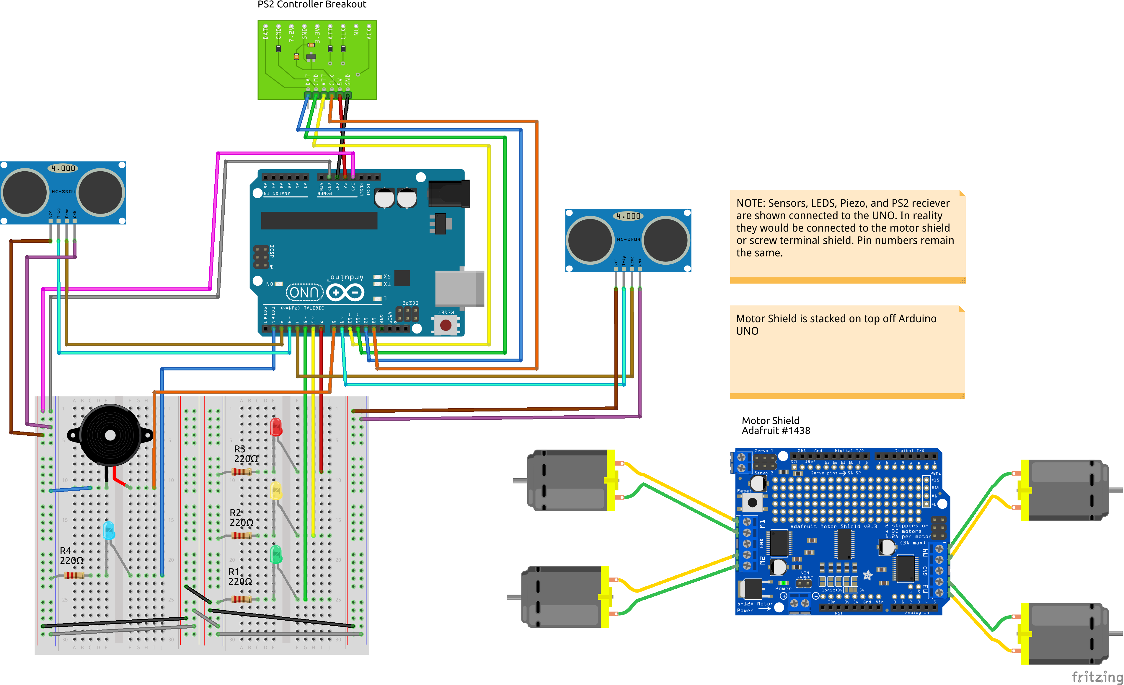
WiringI have attached the wiring schematic for the whole car but it is quite busy. Below is a breakdown of where everything is wired to on the Arduino and motor shield.
DC Motors:
Motor Shield terminals M1 thru M4: positive and negative terminal. (no need to use the GND terminal)
I would recommend checking out adafruits write-up on the motor shield before started. lots of great information.
https://learn.adafruit.com/adafruit-motor-shield-v2-for-arduino/overview
Also with most DC motors, it's hard to tell the direction that you are wiring them. Would recommend tested each motor separately and swapping the wired if it is running in the wrong direction.
PS2 receiver breakout:
DAT -> Pin 12
CMD -> Pin 11
ATT -> Pin 10
CLK -> Pin 13
5V -> 5V
GND -> GND
HC-SR04: (I'm showing you the pins the code uses, but can be attached to any digital pins)
front sensor -
GND -> GND
Echo -> Pin 2
Trig -> Pin 3
VCC -> 5V
back sensor -
GND -> GND
Echo -> Pin 4
Trig -> Pin 9
VCC -> 5V
Red LED:
Anode -> Pin 7
Cathode -> GND
Yellow LED:
Anode -> Pin 6
Cathode -> GND
Green LED:
Anode -> Pin 5
Cathode -> GND
Blue LED:
Anode -> Pin 1
Cathode -> GND
*note: I wouldn't normally use pin 1 but I was out of pins. Because pin 1 and 0 are used for serial communication you can't use the serial library. If you do need to use the serial library consider getting rid of this LED.
Peizo:
Pin 8 and GND
Controlscheme:
Finishedproject:
How this project can be improved:
- Cleaner wiring (maybe using a soldering prototype board)
- More HC-SR04 sensors for object detection on the sides
- Encoders to help account for wheel slip


_ztBMuBhMHo.jpg?auto=compress%2Cformat&w=48&h=48&fit=fill&bg=ffffff)


Comments
Please log in or sign up to comment.