A Surprise Hardware Bug in Raspberry Pi's RP2350 Leads to Unexpected Pull-Down Behavior
Errata include a warning of "latching" GPIO pins when using the internal pull-down resistors, thanks to a faulty fault-tolerant pad.

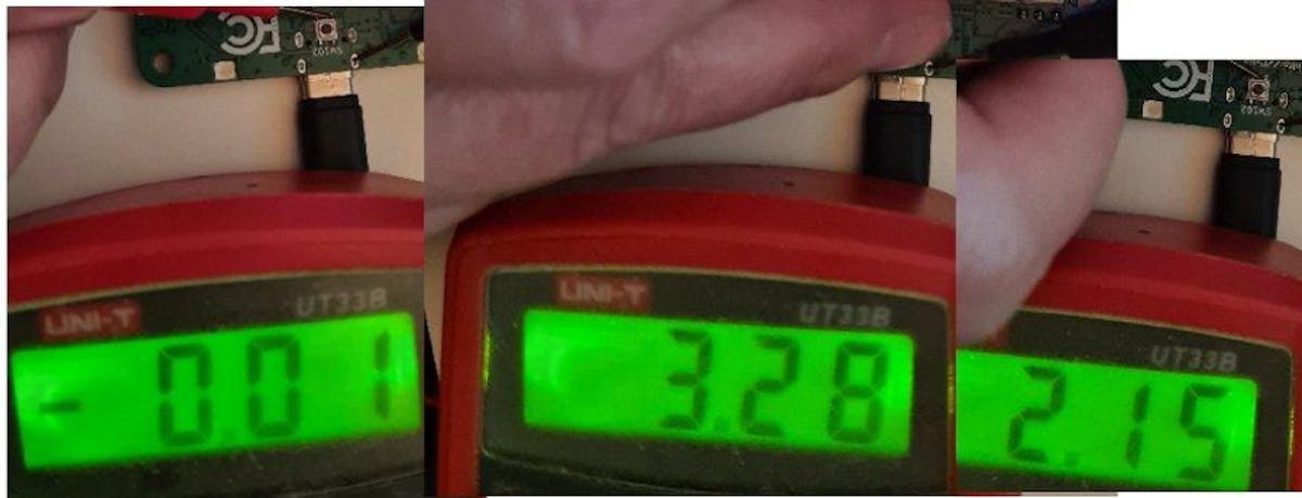
Raspberry Pi has confirmed a bug in the new RP2350 microcontroller family, which causes pins to freeze outputting 2.15V when configured as inputs using the internal pull-down resistors — tied, it seems, to changes made by a vendor to an off-the-shelf fault tolerant pad IP block.
"[I] found a silicon bug," Dangerous Prototypes' Ian Lesnet explains of the issue, which has been confirmed as an erratum in Raspberry Pi's official documentation for the newly-launched dual-architecture RP2350 microcontroller family. "When a GPIO [General-Purpose Input/Output] pin is an input with the pull-down resistor enabled, it acts like a bus hold. We use the pull-down on the button, which connects to 3.3V when pressed. During the self-test pressing the button works, but then it never goes low again, it sits at 2.15V…"
The Raspberry Pi RP2350 family is an ambitious second-generation in-house microcontroller design, and one that blends — for the first time in the company's history — off-the-shelf Arm cores with free and open-source Hazard3 RISC-V cores. The latter were developed by Luke Wren, principal hardware engineer at Raspberry Pi, and are not the source of the problem — which is, instead, being pinned on an unnamed IP vendor.
"We didn't modify the [faulty] pad, we asked the vendor to modify their own pad," Wren explains of the source of the problem, which was traced to the analog circuitry of a particular fault tolerant (FT) pad. "There was one particular structure on the RP2040 FT pad that limited its tolerance, but on inspection the modified layout we got back was a completely different circuit. It was a bit of a blind spot for us in simulation, because the supplied simulation model obviously does not have this issue."
That issue, as detailed in Raspberry Pi's RP2350 datasheet as erratum RP2350-E9, is described as "latching behavior on Bank 0 pull-down resistors," and affects all GPIO pins: when configured as an input that uses the internal pull-down resistor and with the output buffer disabled, a GPIO pin will latch at between 2.1-2.2V rather than be pulled back to ground — but only after its first use.
As the issue is in the chip's hardware, there's no easy fix — with Raspberry Pi stating it will address the issue through "documentation" rather than any changes to the software development kit (SDK). This includes the recommendation to only enable the input buffer immediately before reading, then disable it again afterwards — though, for those who aren't tied in to a particular circuit layout, an easier fix is to configure inputs to use the internal pull-up resistors instead, which are not affected.
In Lesnet's case, the issue was worked around in two ways for the upcoming RP2350-powered Bus Pirate 5XL and Bus Pirate 6. "Buttons were changed to use pull-ups, but we also rely on the pull-downs for open collector bus types," he explains. "The pull-down holds the IO pin low so the PIO [Programmable Input/Output] doesn't need to manipulate the GPIO direction. Boards have 100k pull-downs installed (instead of 1M Ohm) until there is a solution."
Lesnet's full thread is available on Mastodon, as is Wren's comment; more details are available in the RP2350 datasheet, page 1340.
Freelance journalist, technical author, hacker, tinkerer, erstwhile sysadmin. For hire: freelance@halfacree.co.uk.