Adjustable Load PCB
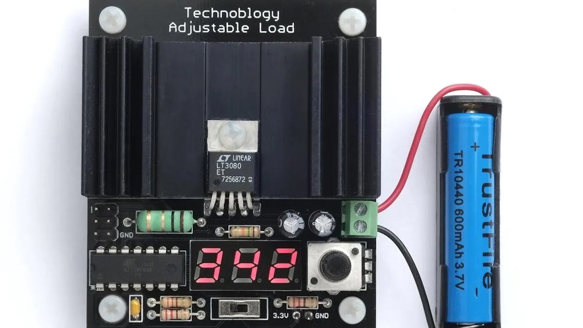
David Johnson-Davies' adjustable load uses an ATtiny84 for display.


If you’d like to test power supply or battery capabilities, one way is to use a high wattage resistor and monitor the output. While this works, it only allows you to use one specific load without hardware changes. Alternatively, you can use an adjustable load to test your device under different conditions.
Technoblogy’s David Johnson-Davies needed just such a setup for two projects he was working on, and rather than buying an adjustable load, he built one himself. The design is based on his previously breadboarded adjustable load circuit, which was lost to the ravages of time, i.e. disassembled.
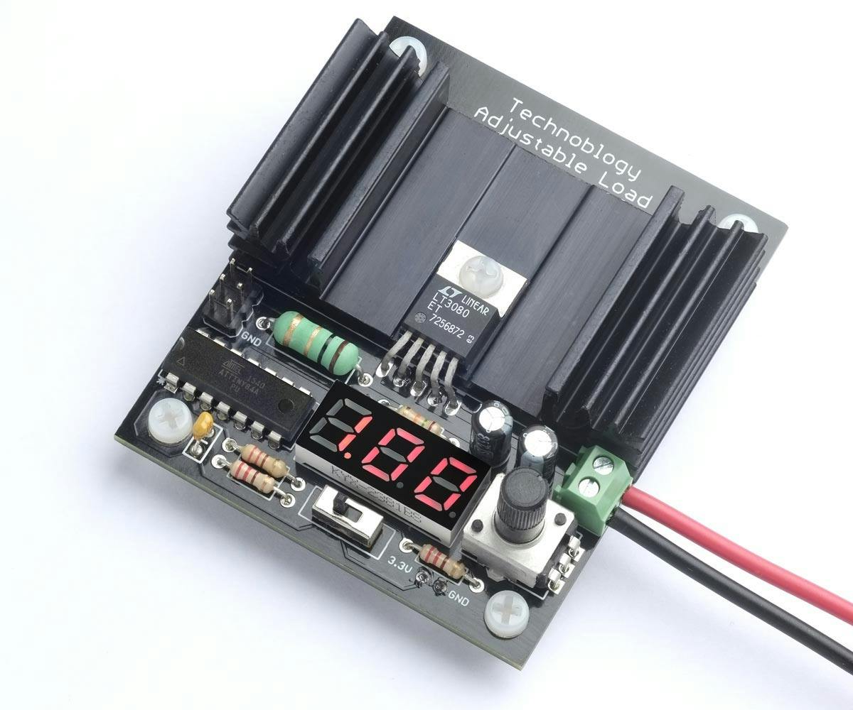
This iteration is nicely integrated into a printed circuit board. Here he considered upgrading to a 0-series ATtiny from the ATiny84, and/or an OLED from the LED display originally used, but decided to instead stick with his proven design.

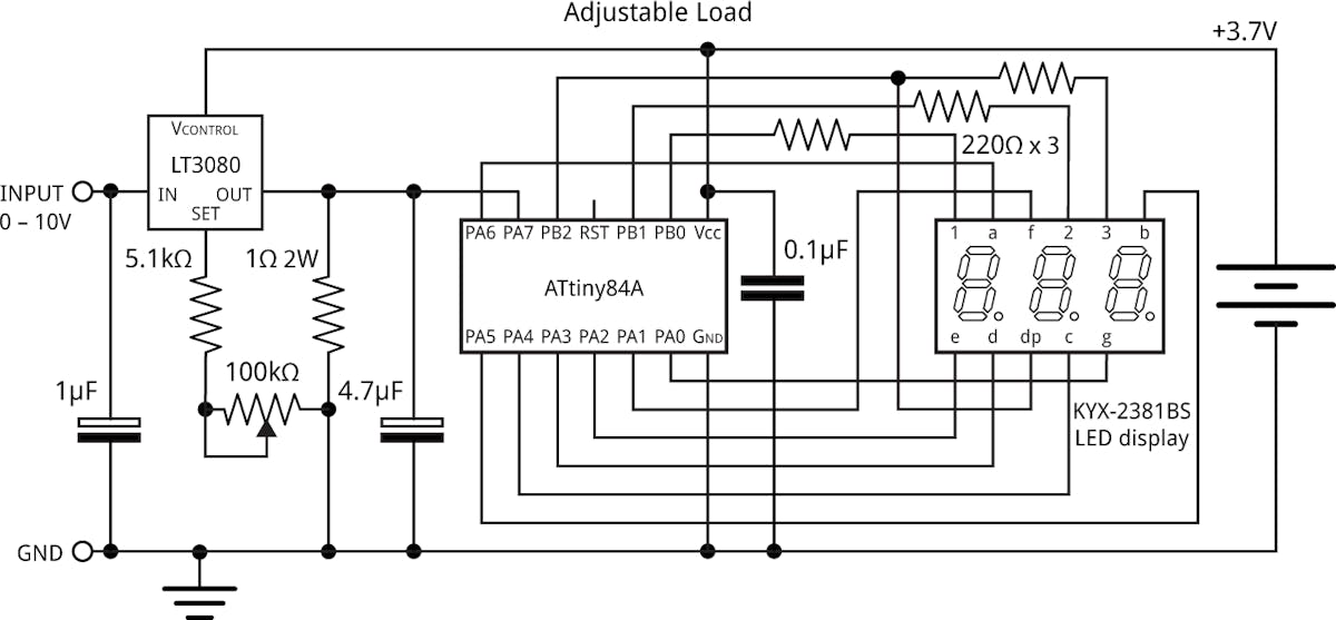
The circuit features an LT3080 regulator to control current flow, which can operate down to 1.5V and a few mA. A separate battery from the supply under test powers the apparatus, which enables it to test down to 1V, and supply the microcontroller even when the tested current drops to zero.
Load current is set via a potentiometer, shown on the seven-segment LED display by the ATtiny84A microcontroller. When a battery under test no longer supplies current, this display then switches to showing the battery capacity.

Code and board files are linked in the Technoblogy post, along with a parts list. There’s also a bit about testing two similar, but differently-labeled, batteries to see if they live up to their specs. The answer may (or may not) surprise you!
Engineer, maker of random contraptions, love learning about tech. Write for various publications, including Hackster!
