Build Your Own RF Lab: Scalar Network Analyzer
A simple scalar network analyzer that can be controlled by a Raspberry Pi for measuring the frequency response of filters and networks.

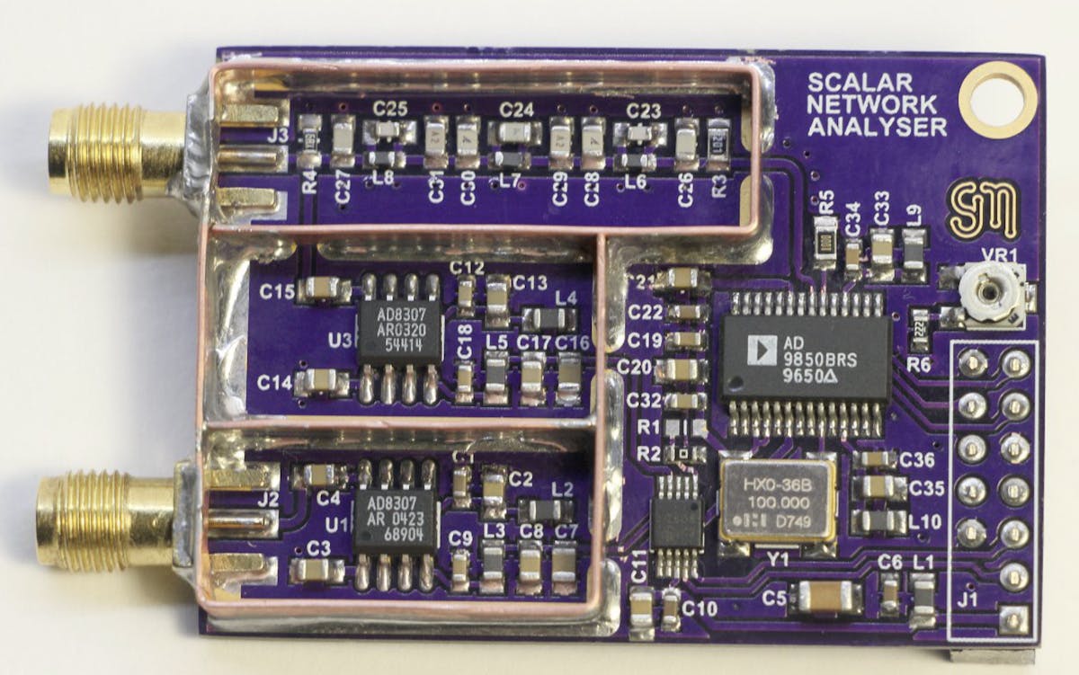
With the popularity of wireless applications having become such a staple in the hobbyist community, the need for RF testing capabilities in the hobbyist realm has also increased. Anyone familiar with traditional RF test equipment knows that it is expensive. But challenges like this are what bring out the engineering creativity in this community. Steven Merrifield designed and laid out his own simple scalar network analyzer (SNA) using just a few IC chips. SNAs are handy for testing the frequency response of filters or networks.
A scalar network analyzer is used to test the amplitude of a device's frequency response by outputting a sine wave sweeping over a certain frequency range (bandwidth) then measuring the amplitude of each incremental output frequency.
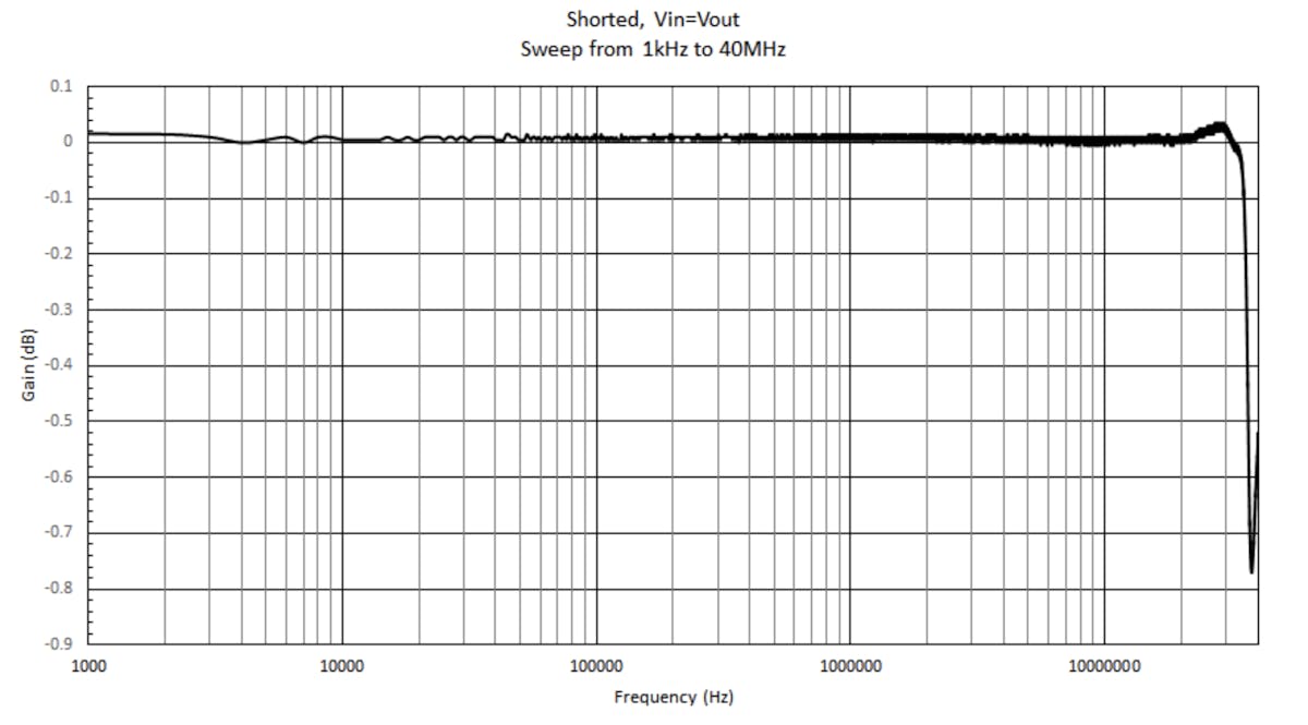
Thus if you directly connect the sine wave output of an SNA to its measurement input, then it will read a flat line of the same amplitude for each incremental output frequency of the sweep:

When a device is connected to the SNA, the amplitude of the sine wave at each frequency after going through the device will reflect the device's frequency response over that bandwidth.
Merrifield's design accomplishes an SNA's functionality via implementation of a DDS Synthesizer chip, an ADC, and a logarithmic amplifier chip. The AD9850 DDS is responsible for outputting the sweeping sine wave while the AD8307 logarithmic amplifier conditions the signal input into the SNA for the log of the signal's envelope before passing it on to the ADC for digitizing. A second AD8307 also conditions the output of the DDS and outputs it to a second channel of the ADC so that it can be used in software for compensation of any variations on the DDS's output due to the effects of various loads of devices being tested.
The ADC outputs its digital measurements via an I2C interface to a GPIO header that matches the Raspberry Pi's GPIO header pinout, but any desired MCU or FPGA could be used. The source code Merrifield wrote is in C, making it easy for porting across different platforms.
Check out Merrifield's project logs here. He linked his PCB layout on OSH Park if you're interested in ordering it and putting one of these together for your own lab!
All thoughts/opinions are my own and do not reflect those of any company/entity I currently/previously associate with.

