Create PCB Coils Using Python and KiCad
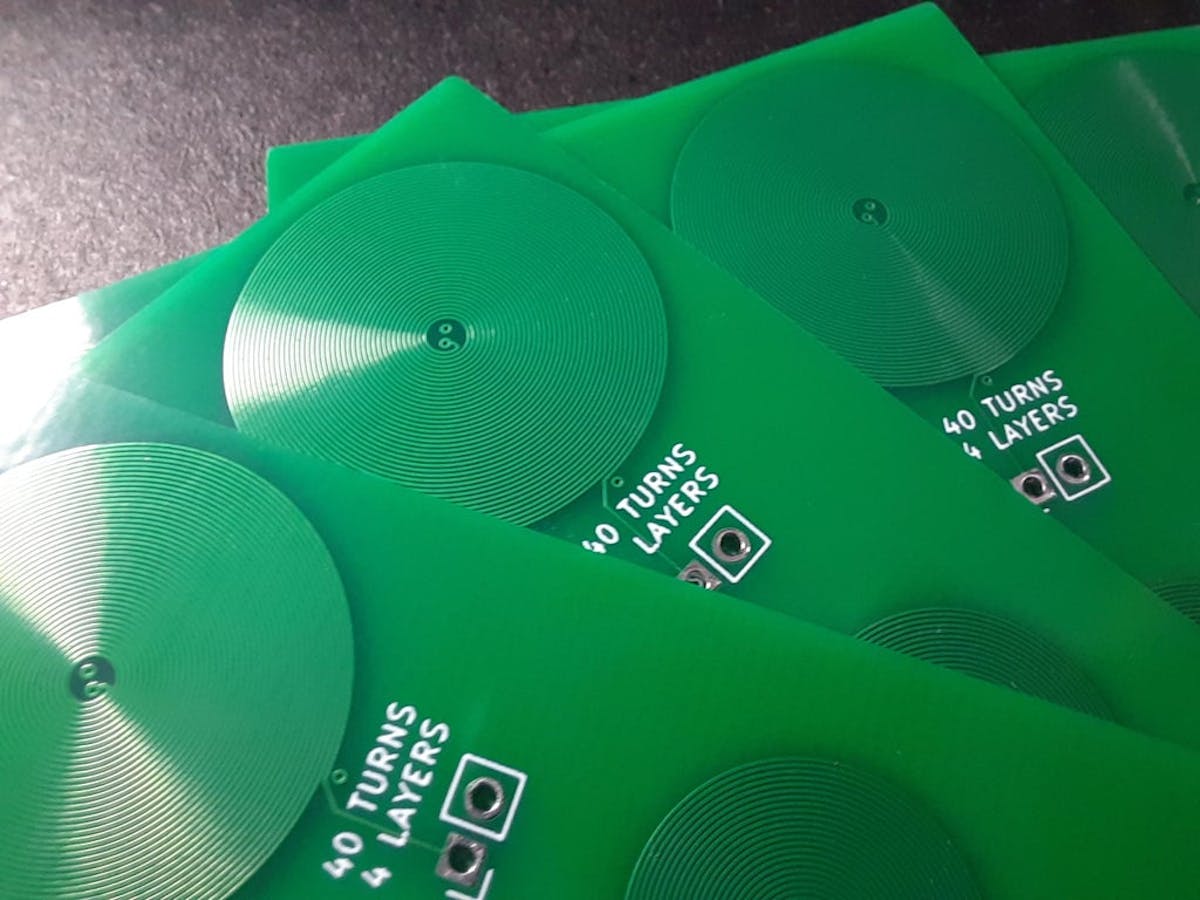
Although KiCad doesn’t like to produce curved traces, its file format is open and text-friendly, so you can make coils using Python scripts.

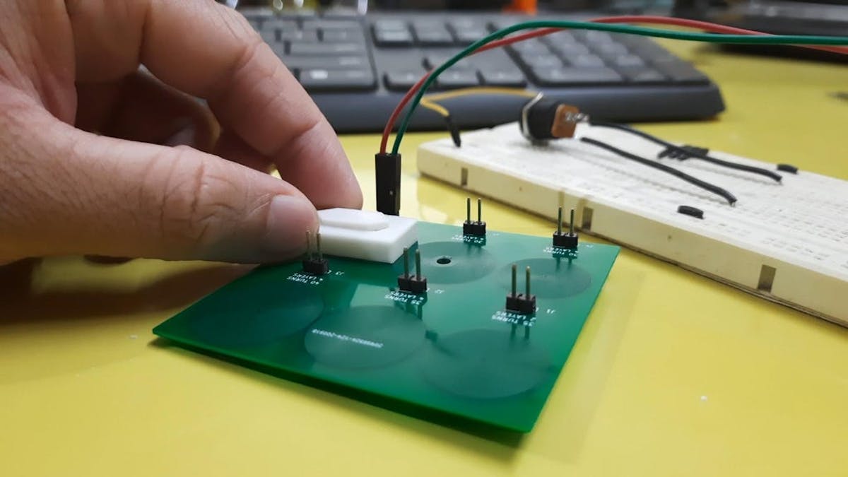
Electrical engineer Neeraj Rane created a mechanical seven-segmented display using electromagnets to push the segments and decided he wanted to improve on the design, as the electromagnets are power-hungry, drawing 9A for each digit. Rane then took notice of Carl Bugeja’s FlexAR project that uses electromagnets on a flexible PCB, or rather coils, and wondered if he could implement his own design to make a smaller display with power-efficient segments.
The idea is that a coil of wire produces an inductance, even if it’s a copper trace on a PCB. Rane can leverage those coils for their electromagnetic properties when generated by a change in the current flow. The problem here is that Rane uses KiCad, an open source PCB design platform, which doesn’t like to play with curved traces.
He then found that if you open a KiCad-generated PCB file in a text editor, each segment is denoted by X and Y coordinates, along with some other information. Now he could use that information to form complete coils, but it would take an excessive amount of time.

Luckily, Rane discovered a Python script written by Joan Spark that could automatically manipulate all those coordinates after entering a few parameters.
“You need to set a few parameters like center, number of turns, copper layer, net number and most importantly, the direction of rotation (spin). While going from one layer to another, the direction must change in order to keep the direction of the current same. Here, spin = -1 represents clockwise while spin = 1 represents counterclockwise,” he notes in his Instructable. “Run the script, and you will be presented with a lot of numbers in the output window. Copy and paste everything into the PCB file and save it. Open the PCB file in KiCad, and there’s your beautiful coil.”
