Miniature Breadboard Voltmeter
Curious Scientist's two-channel mini voltmeter plugs into breadboard for easy voltage readings.


When you set up a project on a breadboard, you often need to read voltage outputs at different junctions. A traditional handheld voltmeter does the job adequately, but also takes up precious space on your bench-top. You’re also restricted to viewing just one voltage channel at a time, which can be inconvenient.

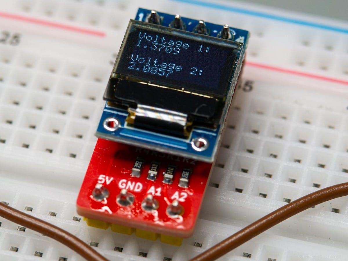
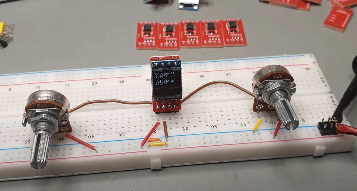
To address both challenges, Curious Scientist developed a tiny PCB-based voltmeter that attaches to your breadboard, taking up a minimal amount of space. The device plugs into four pins on a breadboard, two of which supply power at up to 5V and GND, while the other two input to-be-read voltages at A1 and A2 for circuit analysis.
The voltmeter uses an LDO to reduce the input supply voltage to 3.3V at the microcontroller, an eight-pin CH32V003J4M6. For each analog input, the device employs a voltage divider with 10k and 3.9k resistors, allowing it to measure values between 3.3 and 12V without issue.

The device looks great in the video below. Its 12x24mm PCB, which mounts a 0.42" 74x40 pixel OLED, takes up very little breadboard room, especially when implemented vertically with 90º headers.
Programming is done via a breakout for the chip’s SWIO pin on the side of the PCB, along with GND and 3.3V. There are also breakouts for 3.3V, GND, SCL, and SDA on the side opposite the analog breadboard pins, which could be used for future expansion. The main mini-voltmeter writeup is found here, and this separate post elaborates on programming the CH32V003J4M6 for voltmeter usage.
Engineer, maker of random contraptions, love learning about tech. Write for various publications, including Hackster!

