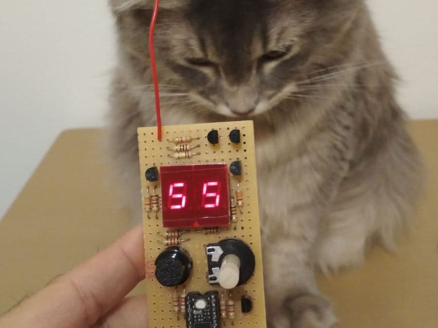
Some cats tend to be so electrostatic, that I often get shocked when petting them. :) I just wanted to create a funny and rather useless tool, that allowed to measure the electrification when you pet them!
Of course this is not a precise meter. The value displayed is just in arbitrary units!
I used uChip, but you can use anything that has an ADC and enough GPIOs.
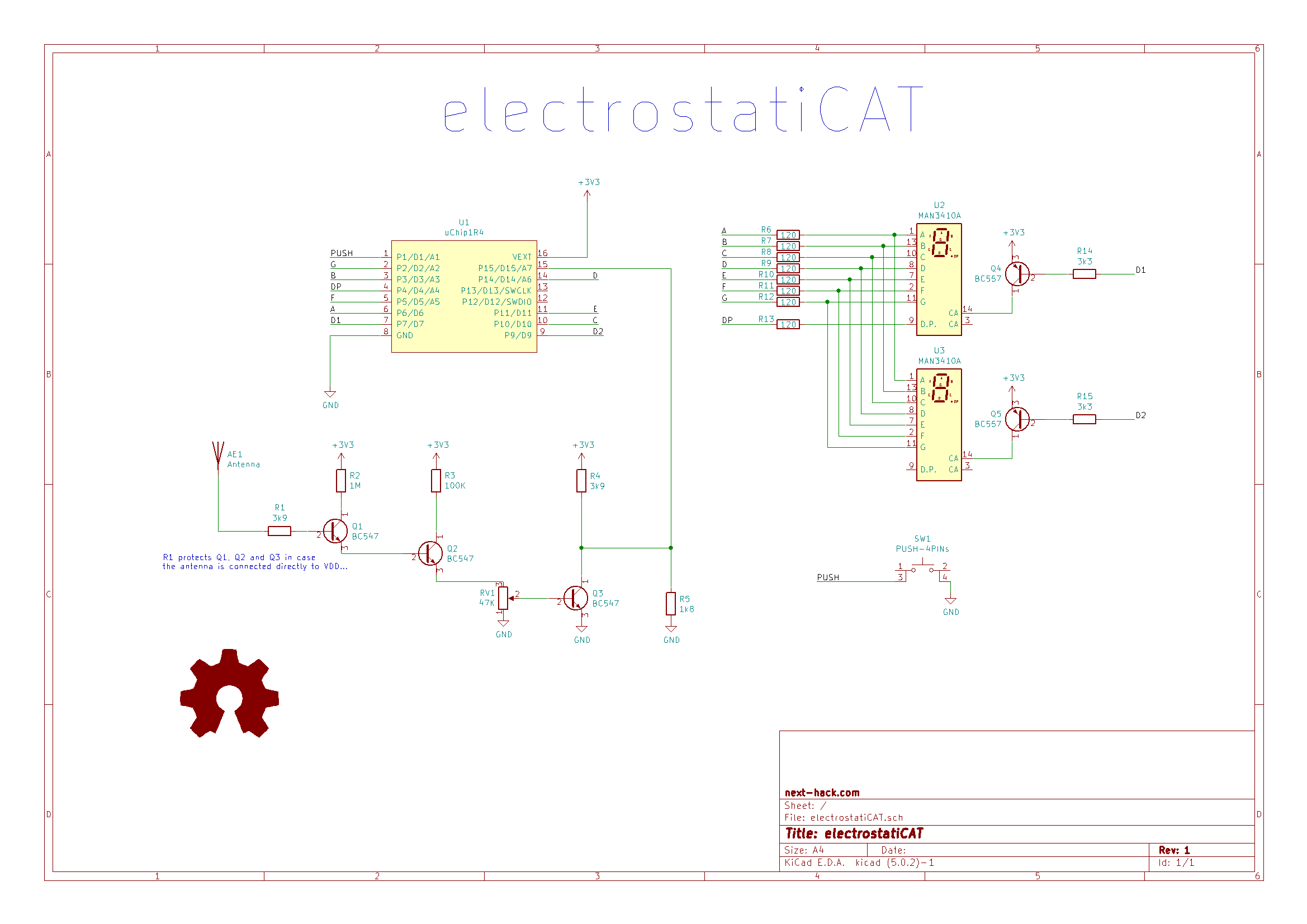
Theory of operationA cascade of three NPN BJTs (Q1-Q3) implements a very sensitive amplifier. This can sense very tiny currents, even induced by displacement of charge, in presence of relatively high electric fields. An even better solution would be using a JFET.
The first two BJTs (Q1-Q2) work as emitter followers, while the last one (Q3) is a simple common emitter. When no current is injected into the base of Q1, Q3 will be OFF, therefore the output voltage is high. On the contrary, when current is injected into the base of the first BJT, Q3 will be turned ON (up to saturation). A collector to emitter resistor (together with the collector resistor) translates the 0-3.3V into a 0-1V voltage, which is the reference voltage range used by the internal DAC of the ATSAMD21.
Between the second (Q2) and third stage (Q3), a potentiometer is inserted to regulate the effective sensitivity.
For a compact design I used uChip which fits a 16 pin IC socket.
The ATSAMD21 also drives a couple of common anode displays. The displays are multiplexed, i.e. they share the cathodes of each segment (A-G), but their common anode is individually selected by the signal D1 an D2, which control two PNP BJTs. You can add any number of displays, but keep in mind that the combined output current for all the 7+1 segments should not exceed 65 mA per pin cluster, according to ATSAMD21. Increasing the number of digits, you'll get dimmer displays, so you'll require higher display currents.
The program is simple: after initialization, it performs continuous measurements on the ADC.
The instantaneous ADC value is shown by the luminosity of the built-in LED. It is also integrated and displayed on the displays. The pushbutton resets the counter to zero.
Finally, the circuit is USB powered.
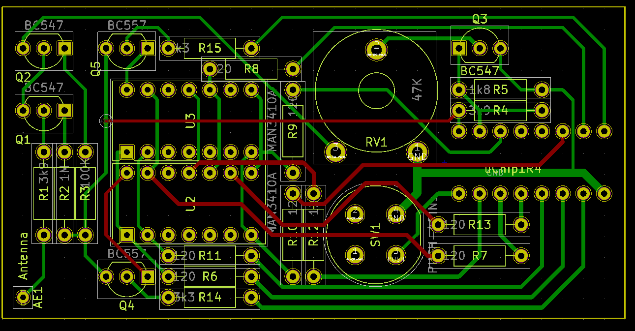
You can either use the KiCad project and have the PCB manufactured (you can manufacture it by yourself, as the design rules are very relaxed), or you can use a perfboard. You'll require a lot of wires in the second case, and in this case it will be a bit difficult.
I suggest as always to mount the components in order of height. Resistors, IC socket, BJTs, etc. Then create the connections: use the component wires you cut after soldering, to create the connections. When no space is available, use of course insulated wires.
When adding wires, be aware to keep some clearances between the top two transistors and the rest of the circuit. They are very sensitive to noise pickup!
Finally, solder the antenna: a piece of wire. I suggest to bend the final part, to avoid hurting the cat.
As you might see, I attached on the displays a piece of red transparent plastic. This is useful to strongly increase the contrast ratio: smaller currents are required for the same apparent luminosity!
After soldering, just upload the provided sketch, and that's it!
Now let's test it!


Comments
Please log in or sign up to comment.