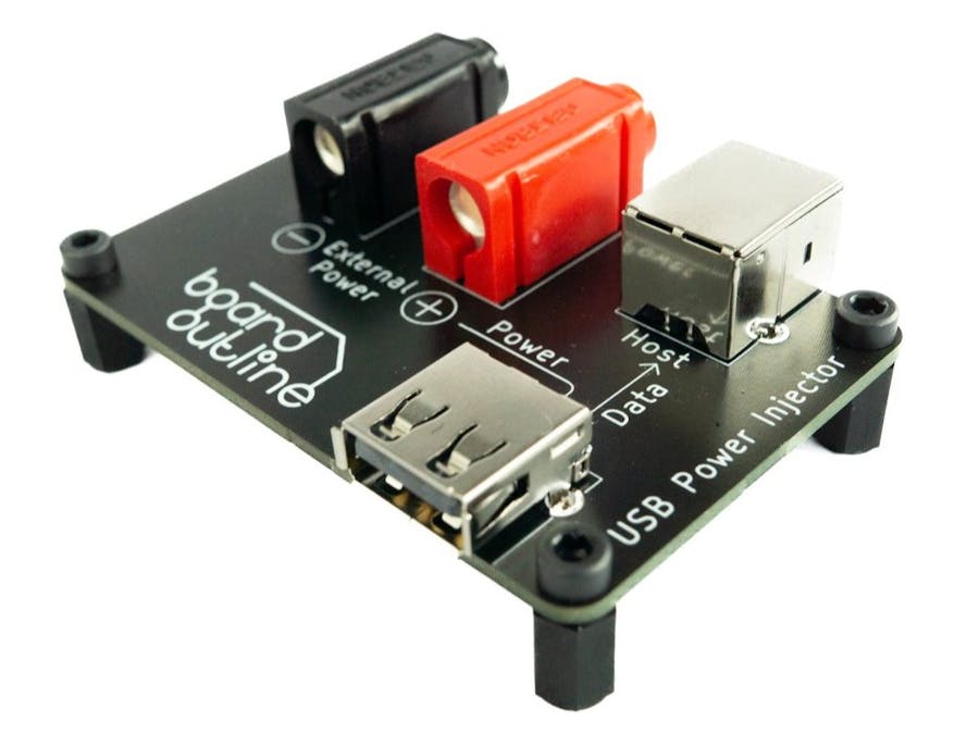
When powering devices from a standard USB 2.0 port, either from a PC or from a standard USB hub, you never have the niceties that an adjustable lab style power supply has. During development that means you can’t set precise voltage and current limits. In the best case scenario, that means you can’t test under/over voltage protections. In the worst case, you run excessive current trough your device and you don’t even know that’s happened.USB hubs tend to have overcurrent protection, but most don’t send the overcurrent event to the operating system.That can cause confusion and loss of time for a hardware engineer during development or to testing personnel during production.This project allows a way to conveniently power a USB2.0 device from a lab power supply and thus avoiding the problems described above.
Schematic DescriptionThe schematic for this project is quite simple.
There are two USB connectors. USB A - for a connection to the device under test and USB B - for a connection to the host. The two USB connectors are connected with a differential pair as denoted by D_P and D_N.
The USB A connector gets its power from the two 4mm banana jacks - one black and one red, in order to denote polarity. This allows the device under test to be powered from an external lab power supply with just 2 standard banana to cables, like the once showed in the photo.
The layout is equally simple. In order to route the USB traces at 90ohms impedance, the JLC7628 stack up was used. The traces were routed with a spacing of 0.127mm and width 0.2mm, as per JLC's impedance calculator. Layers 2 and 3 are ground plains. Yes, this board work just fine as a 2 layer board, since the traces are short, but 4 layer boars are cheap and I wanted to get the required 90ohms impedance, as specified in the USB2.0 standard.
I designed the silk screen to be as descriptive as possible for anyone using the board. It describes both the power path and the data path.
Basic usage and slow dynamic current measurement.In the first test we are going to explore a basic use case for the USB Power Injector. As shown in the video, we have an Arduino Nano connected to a PC running the Arduino IDE. At the same time, the Nano is powered by a benchtop PSU and we can set its supply voltage and a protective current limit. This setup allows for full control of the Arduino, both in terms of how we power it and how we communicate with it. A new firmware can be uploaded, as shown in the video (I change the blink time). It also allows for communication via the virtual COM port.
This setup also allows for some slow dynamic power measurements. A milliamp meter is connected in series with the Arduino, in order to measure the supply current more accurately. When the Arduino LED is off, the board draws 27.2mA and when it’s on it drawn 32.5mA. This functionality can be quite useful to roughly determine what state a board is. For example, if a wireless transmitter is off, the product under test will draw less current.
For general purpose development work I usually skip the amp meter and just use the amp meter embedded in the power supply.
I'm extremely happy to announce that I have started a CrowdSupply campaign in order to get the USB Power Injector to people who would find it useful. If you are interested feel free to check it out at CrowdSupply. Now to the experiment
Fast dynamic current measurements
For some measurements using just an amp meter to capture current draw may be insufficient. Let’s say we are trying to capture the maximum current drawn by a Wi-Fi module while it’s making a HTTP request. Let us explore this exact task using a module with ESP8266 Wi-Fi enabled microcontroller, Micsig CP2100B current probe and a scope.
The module is programmed to make an HTTP request every second.
As we can clearly see, capturing the maximum current draw is trivial. As well as capturing how often and for how long the transmitter is turned on. This could be of great help when developing battery powered devices, where minimizing the power draw is paramount. Since the USB Power Injector uses standard 4mm banana plugs, it would be equally easy to use a different kind of current probe. For example it would easily interface with popular uCurrent Gold developed by Dave Jones.


Comments
Please log in or sign up to comment.