IntroductionBelow is a detailed tutorial on creating a crude bike accident detector and notification system. This build should be able to detect when a bike accident has occurred through the values of a shock switch sensor and tilt ball sensor. The notification system relies on a Particle compatible IFTTT applet.
Argon and Breadboard Setup- First, connect the Particle Argon wifi antenna to the Particle Argon.
- Second, press your Particle Argon into you breadboard with the pins on the left and right hand sides on their respective sides of the gutter.
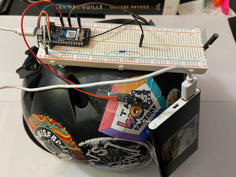
Reference Image for Sensor SetupsParticle Argon with all the components connected
Tilt Ball Switch Setup- Connect one end of the tilt ball switch to GPIO pin D6 using a male to female jumper connector. Note that there is no cathode or anode on the tilt switch so it should not matter which side of the switch is connected to the pin and which side is connected to ground. (Brown wire)
- Connect the other side of the tilt switch to an unused row on the breadboard. Use another male to female jumper connector for this. (Black wire)
- Use a 220 Ohm resistor to bridge this row with the ground rail of your breadboard. The resistor is important so that the switch will not draw too much voltage.
- Finally, connect the ground rail to the breadboard row with the ground pin in it. (White wire)
Three Pin Shock Switch Sensor Setup- Connect the left most pin on the shock sensor denoted with a "S" to GPIO pin D2. Use another male to female jumper cable for this. (Green wire)
- Connect the center most pin on the shock sensor to the VUSB pin on the Particle Argon. This will send 5 Volts to the shock sensor which is used for the sensor's built in pull-up resistor. (Red wire)
- Finally, Connect the right most pin on the shock sensor denoted with a "—" to the ground of the particle argon. The cable can be inserted into the ground rail or directly into the row where the ground pin on the Particle Argon sits. (I found that most of the ground rail holes on the my breadboard fit quite loose, and the shock sensor ground wire would come out from time to time. there was a better connection for me when I inserted the wire directly into the row, so this is what shows up in the photos below) (Orange wire)
Finalized Hardware
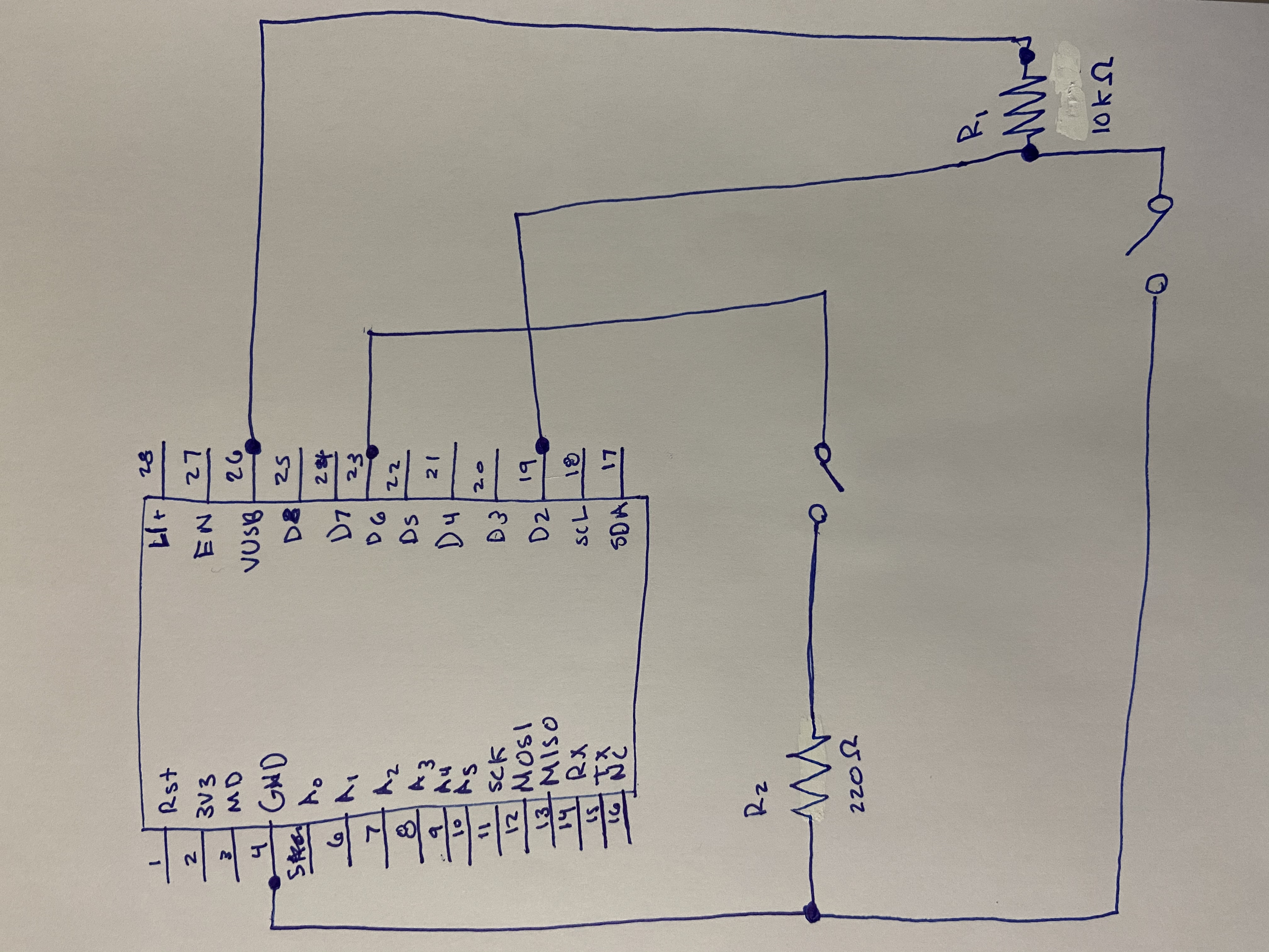
All wire connections into the Particle Argon
- First create your particle variable that will later be used by the IFTTT Applet. Include the line below in your setup function
Particle.variable("crashDetection", crashDetection);
- The line of code above has two parameters. The first sets the name of the particle variable, this can essentially be anything 12 characters long. The second parameter is the name of the variable we are passing to the Particle Variable. The value that is stored in the crashDetection variable is now stored in the Particle Variable. The value of the Particle Variable will remain consistent with the value of the value of the local crashDetection variable even if the local variable's value changes. (I chose to set the Particle Variable name equal to the name of the local variable for the sake of simplicity)
- To finalize this setup, make sure you flash code with this Particle Variable in it to your Particle Argon. This will make sure that you can use the variable in your IFTTT applet
- Next, log into https://ifttt.com/home and click "CREATE". For the "If This" part, choose Particle as the service and select "Monitor a Variable". Fill in the values of the page it sends you to with the values from the screenshot below.
- For the "Then That" part of the Applet, feel free to choose whatever notification service best fits you. My tutorial follows the email service, but with a little tweaking it will fit most others. Select email as the service.
- Fill out the subject and body of the projected email with whatever best fits you since it will not change the effectiveness of the program or notification. I left mine with the default email subject and body because the variable name I had chosen, crashDetection, is descriptive enough of a notification.
Helmet Installation- To make this process easiest and feasible for something long term, I suggest using a smaller breadboard as well as a BMX type helmet that has large flat surfaces. It is hard to connect a flat breadboard to the curved surface of a helmet.
- Side note, I used scotch tape and packing tape to connect my breadboard and components to the helmet because I need to reuse these components for later projects. I would advise using glue and the adhesive part of your breadboard if you intend to create this beyond a simple proof of concept.
- First, secure your breadboard to a flat surface on your helmet. I did this with a loop of packing tape on the bottom. It is certainly not the most secure; I would suggest using glue and the adhesive part of the breadboard for a permanent fixture.
Breadboard Secured with Tape. Loose sensors have yet to be secured to the helmet.
- Next, I secured the tilt sensor in an upright position so that it will read the proper, expected values during normal riding and during a bike accident.
Tilt Switch Sensor secured in upright position.
- Then, I secured the shock switch sensor to a flat part of my helmet using tape. It is important that this sensor is tightly secured to the helmet so that it does not shake during loose motion. If it is tightly secured to the helmet, then you can expect that it will only sense a shock when the helmet senses that shock as well as opposed to a loosely shaking sensor on a relatively steady helmet.
Shock Switch Sensor secure tightly to the helmet.
- Finally, I secured the portable battery to the back of the helmet with the ports facing upwards for short connections between the Particle Argon and power source (Batter Pack).
Battery pack secured to finalized helmet


_zhWsCcSEcl.jpg?auto=compress%2Cformat&w=48&h=48&fit=fill&bg=ffffff)


Comments
Please log in or sign up to comment.