This project is the result of the final assignment in ME 461 (Computer Control of Mechanical Systems), a course offered at University of Illinois.
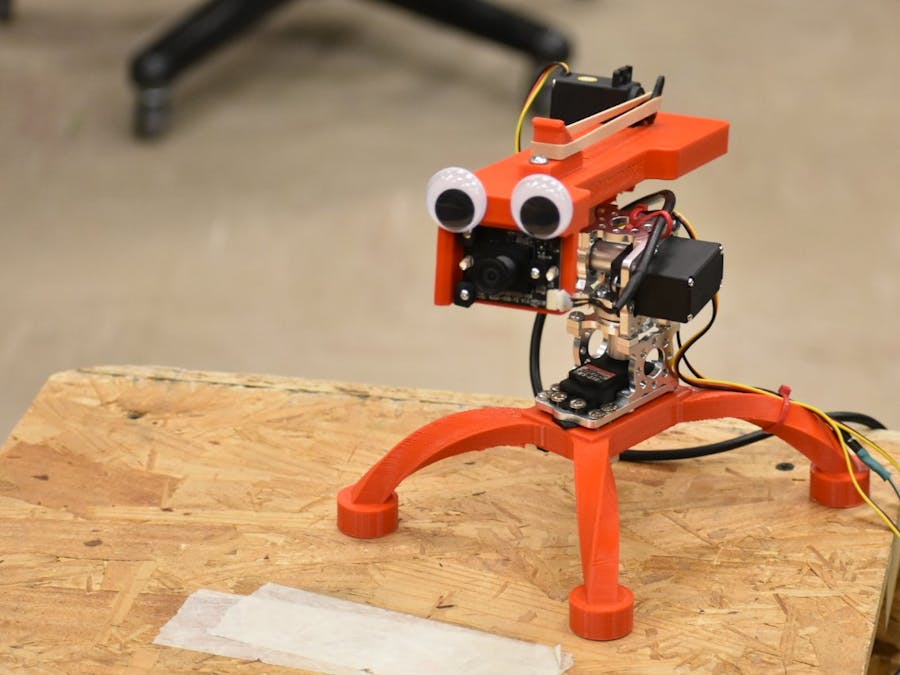
INTROThe Noot Shoot is a a rubber-band shooter on a pan-tilt stage that targets a specific color using computer vision. The pan-tilt stage uses the HiTec HS-311 servos to move and is installed in blocks obtained from servocity. The camera is screwed in front. Another servo is used as a trigger for the shooter.
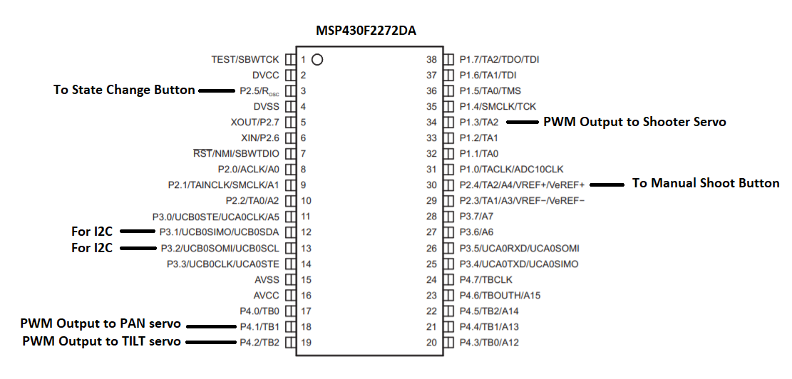
The servos are directed using MSP430, a microcontroller by Texas Instruments, while the Orange Pi Zero is used to interface with the camera. The stage and the legs are 3D printed.
SYSTEM INPUTThe input of the system is a live feed from the camera. The C++ program that runs continuously in the Pi reads this feed frame by frame and calculates the center coordinates of the object we are interested in. In our case, we target a range of colors between a range of HSV values: (239*, 103, 103) and (15*, 255, 255). This corresponds to a bright pink in the HSV spectrum. The program counts all the pink pixels in the frame and calculates the centroid of the object if there are more than 60 active pixels (this is necessary so noise in the environment isn't considered to be an object). These coordinates are sent to the MSP430 using the I2C communication protocol.
The other inputs are the two push-buttons. One is for manual shooting and the other is for changing states. More information is detailed in the next sections.
PROPORTIONAL CONTROLLEROnce the center coordinates of the object are received in the MSP430, the error in the x and y axis is calculated as the difference between the center of the camera frame and the center of the object. The magnitude of the error informs how much turn is needed. As such, we calculate the turnrate as the product of error and a proportional gain that we tune. This turnrate is then subtracted from the previously sent servo command and this new value is set to be the new destination for the servo. We need to subtract as the error and the positive angular movement of the servo have opposite directions.
errorX = 160 - rxlong1; // rxlong1 is the x-coordinate of the object in frame.
errorY = 120 - rxlong2; // rxlong2 is the y-coordinate of the object in frame.
turnrateX = kpx*errorX; // kpx and kpy are gain values that need to be tuned.
turnrateY = kpy*errorY;
currX = prevX - (turnrateX * 20)/1000; //We multiply with 0.02 based on the loop time
currY = prevY - (turnrateY * 20)/1000;We wrap our control program in a state machine. The shooter can be divided into two states. Either it is actively identifying a target to shoot or it is in reload mode where the stage stops moving so the user can load the next rubber band. The shooter starts in the actively looking mode. Following are the conditions which cause the states to change:
From actively looking to reload mode:
Press the state-change button.
- Press the state-change button.
The manual-shoot button is pressed. This launches the rubber-band and the shooter goes to reload mode after a very short delay.
- The manual-shoot button is pressed. This launches the rubber-band and the shooter goes to reload mode after a very short delay.
The error in both x and y axis has been less than a defined threshold for more than 3 seconds. This means either the target is moving very slowly or not moving at all. In this case, the shooter automatically shoots the rubber band and then goes to reload mode after a very short delay.
- The error in both x and y axis has been less than a defined threshold for more than 3 seconds. This means either the target is moving very slowly or not moving at all. In this case, the shooter automatically shoots the rubber band and then goes to reload mode after a very short delay.
From reload mode to actively looking:
Press the state-change button (this is the only way).
- Press the state-change button (this is the only way).
Incorporation of three servos: We used Timer B for the pan and tilt servos. The carrier frequency was set to 20 ms. The timer was set to up mode with the output mode set to reset/set. Timer A was similarly adjusted to control the shooter servo.
Connection of Buttons: We used 2 push-buttons as described above. For this, we defined Pin 2.4 and 2.5 as input pins with resistor enabled and pulled down. The buttons were also connected to a capacitor to prevent bouncing.


_3u05Tpwasz.png?auto=compress%2Cformat&w=40&h=40&fit=fillmax&bg=fff&dpr=2)

Comments