

Hardware components | ||||||
| × | 1 | ||||
Software apps and online services | ||||||
 |
| |||||
Hand tools and fabrication machines | ||||||
 |
| |||||
| ||||||
ITEAD guys made it so easy for us mortals to open their products up and do custom things. I have been given 2 EU Sonoff WiFi Smart Plugs from a friend from my local hackspace so it’s time for hacking Sonoff WiFi Smart Plug and flashing it with Tasmota.
Hacking Sonoff WiFi Smart PlugIf you want to know why would I hack perfectly working Sonoff WiFi Smart Plug – I’d recommend you read this article.
Hardware
The Sonoff WiFi Smart Plug is simple to open, 3 screws protect the socket inner PCB from my curious fingers. Inside, you will find a separate ESP8266 board attached to the main PCB where the relay and transformer are located.
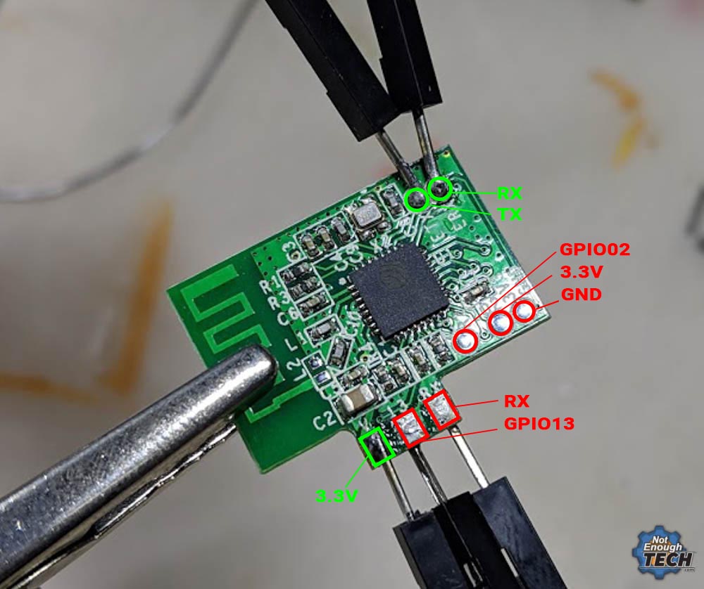
What’s interesting, unlike Sonoff Basic which I hacked previously, this ESP8266 board has more GPIO exposed for further use. I’m sure, I will take advantage of this in the future. Apart from RT, TX and GPIO00 needed for the flashing process, the Sonoff WiFi Smart Plug has devs pads for GPIO04, GPIO05, GPIO02, GPIO12 and GPIO13. That’s a lot of sensors to connect, maybe even a display!
To flash the board, you don’t actually have to remove the ESP8266 from the main PCB, however, I have done so to inspect the board properly. You can find the VCC and GND at the bottom of the board, and use the existing button of the device to pull the GPIO00 to ground. (hold the button down while powering up the ESP to enter the flash mode)
Since soldering took only a couple of extra minutes, I removed the board and attached the wires as shown below.
FlashingMake sure to make a backup of the firmware, that backup is device specific, so if you fail to do so, say goodbye to the eWelink app. Download the sonoff-tasmota firmware and put it into the esptool folder. You can read about setting up the esptool and correct procedure here. In short, just run these 3 commands, each time resetting the board into the flash mode
Once the new firmware is done, disconnect I disconnected the GPIO00 from the ground and rebooted the ESP to see if I can see the new AP. The device was advertising the WiFi so I knew everything went ok.
It was time to reverse all the steps and put the device back together. The entire procedure takes about 20-30 min depends on how good you are with the soldering iron.
Setting up TasmotaTasmota works with Node-RED and couple of other systems. I have entire procedure explained in the separate tutorial – read it here how to set up your Sonoff WiFi Smart Plug. Depending on how you want to control the Sonoff WiFi Smart Plug, you probably want to enable MQTT to integrate the devices with Node-RED.
The device should be configured as Sonoff SX2 in the Tasmota firmware, it will also work as Sonoff Basic.
Works with Node-REDAnd to get you started, I wrote a very simple controller with the web interface. I can toggle the lights using the Amazon Dash Button or the web interface.
The Sonoff WiFi Smart Socket is linked to the 192.168.1.163 so if you want to use the flow I made, make sure to update your IP configuration. I have included the MQTT examples, a showcase how to control the socket via HTTP and added the online status (IP turns red if the socket is offline). If you are interested in Alexa, check this write-up out.
Conclusion
Sonoff WiFi Smart Socket is yet another example of an open-source design that is not afraid of the community modding. This smart socket is fairly easy to hack and flash custom software. It takes very little time and the integration with Node-RED is just excellent. If you want to learn more how to control Node-RED with other devices, check out the connectivity guide in my Node-RED for beginners.
If you want to get the latest updates to this project you can follow me via your preferred social media:
And if you feeling like buying me a coffee or supporting me in a more continuous way:
I hope you have enjoyed the project!


Comments