This project began as a simple request, I wanted the ability to cut metric threads on my Atlas Craftsman lathe and eliminate the hassle of manually changing gears for the lead screw drive. After searching the web I could not find good information on making or buying an electronic lead screw so I decided to start make one. In addition, I decided to add a VFD to control the motor spindle speed.
Since the VFD driven spindle is a separate system to the electronic lead screw I broke it down into two parts: the spindle drive system and the lead screw drive system.
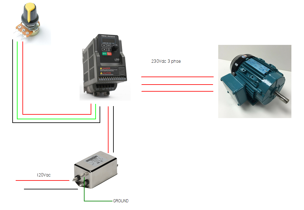
The spindle drive system is pretty straight forward. Replace the single-phase drive motor with a three-phase and drive it with a VFD.
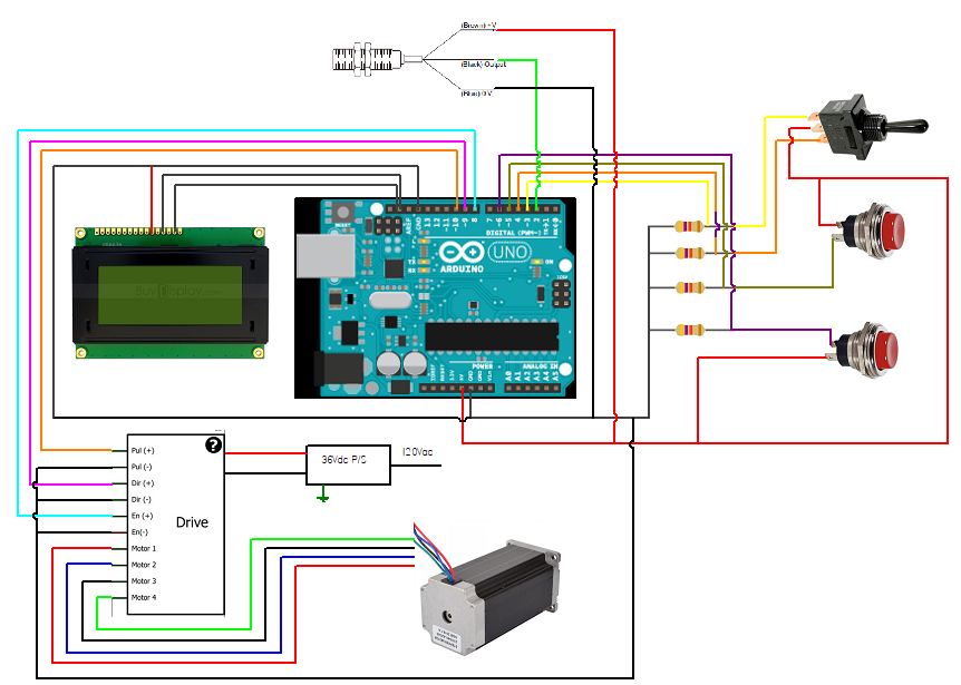
The lead screw drive system uses an Arduino to create a sort of electronic gearbox. The Arduino reads the spindle speed and adjust the servo RPM to match the correct ratio based on user input to create either metric or English threads. An LCD display was used along with two momentary push buttons for the user interface. This allows the user to select either metric or English units and thread sizes. Once the desired thread or pitch is selected a 3-way switch is used to turn the motor in either CW or CCW direction. Once the motor is running the LCD does not update and you cannot change the thread pitch until the motor is stopped.
Spindle Drive System (VFD)I decided purchase a 1/3hp 3ph motor and VFD kit from eBay, the motor frame size was similar to the existing 1/2hp 1ph motor so it was a direct fit.
For the drive system I also purchased an inline EMI filter (this TECO VFD puts off alot of noise and was interfering with the Arduino). The EMI filter was placed on the power supply side to the VFD.
Ferrite rings were used to reduce noise going from the VFD to the motor.
An on/off switch was used to provide power to the spindle and lead screw drive systems. This was mounted on the panel door.
The VFD can be used with an external potentiometer as well which is needed to control the motor speed while operating the lathe. The 10k pot works well. it was mounted on the Arduino enclosure.
These items were assembled into a nema 4 enclosure and wired together (I'm a mechanical guy, pay no attention to the birds nest of wire).
A 24v 20 a power supply was used to provide power to the stepper motor (you could probably go with a lesser amperage P/S). The power supply was mounted in the VFD enclosure.
I decided to go with a NEMA 23 stepper motor with 3Nm of torque, If I could do it over again I would have stepped up to a NEMA 24, this motor has just enough power to cut threads without stalling.
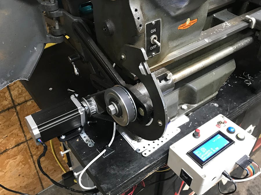
A steel mounting bracket was used to mount the motor on the lathe work bench
A 14t 3/8in L timing pulley was used for the pinion drive on the stepper
For the timing pulley on the lead screw I used a 22t 3/8in L timing pulley with a taper lock adapter. The adaptor had a 0.75in bore with the same keyway that matched the existing lead screw. No modifications to the lathe were necessary.
Below is a picture of the stepper motor with the synchronous belt system. I cut out bottom of the safety door to fit over the stepper motor so it can be closed.
I used a microstepper driver to interface between the Arduino and the stepper motor. The driver uses the 24v power supply to pulse the stepper based on the signal from the Arduino. I simply mounted this on the underside of the bench near the stepper. I did not put it in the VFD panel since there was too much EMI.
To measure RPM of the spindle I used this inductive Hall effect sensor. Since it came with its own LCD I was able to use it to calibrate the Arduino speed calculation. I glued the magnet to the spindle as show below.
I used a small plastic case to house the LCD screen, Arduino, breadboard, and switches.
Plastic case
Arduino
LCD
Push buttons
3-way switch
The program has a few functions. The LiquidCrystal_I2C library and AccelStepper libraries were used. The screens are setup using an array so it is scalable. It uses the X variable to denote metric vs. English and the y variable prints each data field on the screen.
const int x = 2;
int currentX = 0;
String screens[x][5] = {{"TPI","Dir","LatheRPM ","ServoRPM","tpi/mm"}, {"Pitch","Dir","LatheRPM","ServoRPM","tpi/mm"}};
The set button flags loop uses a for loop to read the push button states and signal if a state has changed.
void setButtonFlags()
{
 for(int i=0; i < n; i++)
 {
   buttonState[i] = digitalRead(buttonPin[i]);
   delay[1];
   if(buttonState[i] != lastButtonState[i])
   {
     if(buttonState[i] == HIGH)
     {
       //Serial.print("Button: ");
       //Serial.println(buttonPin[i]);
       buttonFlags[i] = HIGH;
     }
   }
The resolve button flags triggers a push button action if a button has changed state.
void resolveButtonFlags()
{
 for(int i = 0; i < n; i++)
 {
   if(buttonFlags[i] == HIGH)
   {
     buttonAction(i);
     buttonFlags[i] = LOW;
     printScreen();
   }
 }
}
The button action loop determines what to do when a certain button is pressed while a certain screen is displayed. So when you are on the metric screen and you press button A the pitch will change. If you are in English the TPI will change.
void buttonAction(int button)
{
 if (button == 0)
 {
   if (currentX == x-1)
   {
     currentX = 0;
   }
   else
   {
     currentX++;
   }
 }
 if (button == 1)
 {
   if (currentX == 0)
   {
     if(currentTPI == nTPI-1)
     {
       currentTPI = 0;
     }
     else
     {
       currentTPI++;
     }
   }
The speed sensor loop uses a debounce to trigger the calculate spindle RPM loop and stepper RPM loop. The stepper RPM will only change once per spindle revolution. Again, depending on which screen you are on it will either calculate English or metric.
void speedSensor()
{
 time = millis();
 int currentSensorState = digitalRead(SensorPin);
 if (currentSensorState != lastSensorState)
 {
   lastDebounceTime = millis();
 }
 if ((millis() - lastDebounceTime) > debounceDelay)
 {
   if (currentSensorState != sensorState)
   {
     sensorState = currentSensorState;
     if (sensorState == LOW)
     {
       calculateRPM(); // Real RPM from sensor
       if (currentX == 0)
       {
         englishCalc();
       }
       else if (currentX == 1)
       {
         metricCalc();
       }
     }
   }
 }
The send data loop operates while the stepper is not running and is used to send the information to the LCD screen. While the stepper is running this loop is not active since it slows down the processor of the arduino.
void sendData()
{
 unsigned long currentMillis = millis();
 if(currentMillis - prevMillis >= interval)
 {
   prevMillis = currentMillis;
   lcd.setCursor(9,2);
   lcd.println(lcdRPM);
   lcd.rightToLeft();
   lcd.print("   ");
   lcd.leftToRight();
   lcd.setCursor(9,3);
   lcd.println(servoRPM);
   lcd.rightToLeft();
   lcd.print("   ");
   lcd.leftToRight();
   lcdRPM = 0;
 }
}
The stepper speed calculations are based on the lead screw threads per inch ( in this case 8TPI), the synchronous belt gear ration ( in this case 1.529), the micro steps (in this case 400), and the RPM.
void metricCalc()
{
   stepperRPM = 1.529 * 0.315 * 400 * RPM * pitch[currentPitch] / 60.00;
   servoRPM = 0.482 * RPM * pitch[currentPitch];
}
// =========================== metric stepper speed =========================
void englishCalc()
{
   stepperRPM = 1.529 * 8.00 * 400.00 * RPM / ( tpi[currentTPI] * 60.00 );
   servoRPM = 1.529 * 8.00 * RPM / tpi[currentTPI];
}
Here is the main loop, once you get the stepper running only the speed sensor loop runs along with a stepper set speed library function and an if statement to stop the motor.
void loop()
{
 setButtonFlags();
 resolveButtonFlags();
 sendData();
 speedSensor();
 if (digitalRead(leftPin) == HIGH)
 {
   //direction = 1;
   lcd.setCursor(4,1);
   lcd.print("CW ");
   lcd.setCursor(9,3);
   lcd.println(servoRPM);
   lcd.rightToLeft();
   lcd.print("   ");
   lcd.leftToRight();
   lcd.setCursor(9,2);
   lcd.println(lcdRPM);
   lcd.rightToLeft();
   lcd.print("   ");
   lcd.leftToRight();
   delay(5);
   stepper.enableOutputs();
   stepper.setSpeed(stepperRPM);
   stepper.run();
   while(stepper.isRunning())
   {
     speedSensor();
     stepper.setSpeed(stepperRPM);
     stepper.run();
     if(digitalRead(leftPin)==LOW)
     {
       stepper.disableOutputs();
       lcd.setCursor(4,1);
       lcd.print("OFF");
       break;
     }
   }
 }
 else if (digitalRead(rightPin) == HIGH)
 {
   //direction = -1.00;
   lcd.setCursor(4,1);
   lcd.print("CCW");
   lcd.setCursor(9,3);
   lcd.println(servoRPM);
   lcd.rightToLeft();
   lcd.print("   ");
   lcd.leftToRight();
   lcd.setCursor(9,2);
   lcd.println(lcdRPM);
   lcd.rightToLeft();
   lcd.print("   ");
   lcd.leftToRight();
   delay(5);
   stepper.enableOutputs();
   stepper.setSpeed(-stepperRPM);
   stepper.run();
   while(stepper.isRunning())
   {
     speedSensor();
     stepper.setSpeed(-1*stepperRPM);
     stepper.run();
     if(digitalRead(rightPin)==LOW)
     {
       stepper.disableOutputs();
       lcd.setCursor(4,1);
       lcd.print("OFF");
       break;
     }
   }
 }
}
*Update*
I added an if statement so that while the program is in cutting/threading mode if you press and hold the blue momentary push button the spindle will run reverse in rapid mode for quick cutting of material.
if(digitalRead(buttonPin[1]) == HIGH)
     {
       stepper.setSpeed(1500);
       stepper.run();
     }
All in all the system works well. If you are cutting threads do not stop the servo motor as this will cause the spindle and lead screw to get out of time. You will not be able to retrace the same thread profile. If I had more time I would have put an encoder on the stepper motor to make a closed control loop so that the spindle and lead screw could be synchronized based on position as well. But this seems to work fine and I was able to cut metric threads with this setup as long as the servo stays running (just disengage the carriage like normal). Below you will find a list of components and basic description of each item to build the project along with schematics.
The wiring diagrams are attached along with the source code. You should be able to put it all these pieces together, upload the code and start cutting metal.
Thanks for reading!
Nick
email: nsr5058@gmail.com


_ztBMuBhMHo.jpg?auto=compress%2Cformat&w=48&h=48&fit=fill&bg=ffffff)


Comments
Please log in or sign up to comment.