


Hardware components | ||||||
 |
| × | 1 | |||
| × | 2 | ||||
| × | 1 | ||||
| × | 1 | ||||
| × | 2 | ||||
| × | 1 | ||||
| × | 1 | ||||
Software apps and online services | ||||||
 |
| |||||
Hand tools and fabrication machines | ||||||
 |
| |||||
COMP/ELEC 424: Mobile & Embedded Systems
John Reko, Darrell Good, Sean Hamilton, and Ryan Pai
Introduction
Instead of constructing a line-following car like the other teams, our group is working on a submersible remotely operated vehicle (ROV) with an integrated camera unit, which we have imaginatively named Titan. Our group aimed to add dynamically adjusted orientation control to Titan by integrating communication with an inertial measurement unit and the ROV thrusters and a feedback control algorithm.
Titan is constructed from a waterproof metal camera housing, which could maybe withstand pressures similar to those found at the depths of the Titanic. The main onboard computer is a Raspberry Pi 4. Twin Diamond Dynamics TD1.2 onboard thrusters give Titan full horizontal control. Communication with Titan is established via a twisted pair, neutral buoyancy cable, which will hopefully prevent any losses of communication on its mission to the Titanic. Ethernet signals are sent to and from the Titan via this 2-wire tether, which requires adapters on either side of the cable to convert the 4-wire signal to a 2-wire coax signal and vice versa.
IMU Communication
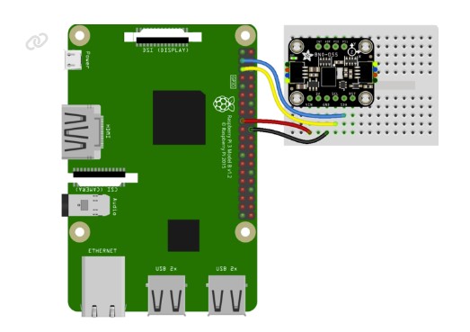
We purchased a BNO055 inertial measurement unit, manufactured by Bosch and packaged by Adafruit. The BNO055 communicates with the Raspberry Pi via I2C. We wrote a serial communication script and API that allows for easy access to the IMU interface, which was part of our version of Project 3. The BNO055 IMU was mechanically fixed to the roof of Titan’s housing with glue.
Motor Control
The Diamond Dynamics TD1.2 onboard thrusters are quite sensitive and require a specific startup sequence. PWM control is established via a 50Hz signal. The pulse width ranges from 1ms (full reverse thrust) to 2ms (full forwards thrust), with a 1.5ms pulse being neutral. Hardware PWM is higher precision than software PWM, and since the thruster control is confined to a narrow range of duty cycles, hardware PWM was critical for precise control. In order to control the motors we used the rpi_hardware_pwm Python library. We found this library while creating our own C PWM driver and we determined that our version of the PWM driver was very similar, making it easier to integrate with the rpi_hardware_pwm library. Under the hood, this library uses the /sys/ pwm interface as implemented by jdimpson. This allows us to control the hardware pwm by echoing commands to the /sys/class/pwm/pwmchip0/pwm file for instance. This however requires that both dtoverlay=pwm-2chan be added to /boot/config.txt that the /sys/ chip path be writeable. Additionally we chose to use the alternate pins for each channel as these were more accessible, so our device tree overlay ended up being the following:
dtoverlay pwm-2chan, pin=18, func=2, pin2=19,func2=2
Initially, when we set the PWM signal to a 50Hz duty cycle and initiated the startup sequence, we received no response from the thrusters. Extensive testing with an oscilloscope revealed a 53.3 Hz frequency when we set the frequency to 50 Hz in software, meaning that we had to set the frequency to 46.7 Hz in software to achieve ~50 Hz frequency for the duration of the project. We are unsure what caused this variation from the nominal value, but we assume manufacturing variations in the crystal to be the cause.
Integrated Control System
We used a proportional-integral-derivative controller, which we implemented using the simplePID package from pip. The controller script takes as an argument the desired change in angle in degrees, from -180° to +180°. The controller script then takes the current absolute orientation from the IMU, computes the desired angle, and uses the PID controller to modulate the input signal duty cycle on the thrusters’ PWM input.
One issue that we ran into was the power we were delivering to the thrusters. From our testing we discovered that the amount of power being delivered based upon the PWM was far too high to reliably slow itself down once the desired angle had been achieved, which led to the camera thrashing back and forth to find the desired angle. To deal with this we first reduced and capped out the values for the PWM that were being sent to the thrusters. From here we found a similar problem and as a result reduced the proportionality component of the PID so that our system would start to slow down further away from our desired angle and thus make it less likely to overshoot. Once we had this implemented, the cam suffered from not keeping steady. While it was still within our desired angle range it was jittering within it, at which point we implemented some derivative gain to correct for the very slight overshoot and led to the camera staying stable in the water. A video of the unstable, pretuning operation is shown here, and a video of our final version is available here.
Testing
Although the frigid waters of the North Atlantic would be ideal for testing Titan, due to budget constraints we were forced to test in the Dunc Tank instead. Shortly before testing, we experienced a catastrophic failure of one of the coax-ethernet adapters, and we were forced to spend several hours debugging and repairing the device. However, we were able to identify the broken component, replace it and maintained full control of Titan via SSH for the duration of testing. The video below illustrates the precise and continuous control that we designed for Titan.
Final Notes
Since this project and its components were funded separately, no parts returns were required.


Comments
Please log in or sign up to comment.