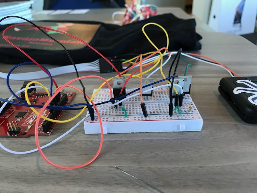
As an Octoblu intern (going to school for fashion) naturally, I have always wanted to integrate my interests here at work to the affinity I have to garment design. Since, I already own my clothing brand (NavajoMermaid.com), I thought it would be super unique if I could get one of my graphics to actually light up on a t-shirt! After spending some time researching ways to automate graphics on a t-shirt; I found that using el wire would most likely be my best alternative! After finding this, I then proceeded to purchase my own shirt on a website that I recommend to everyone which is called, http://www.nitelifetshirts.com! I chose this company mainly due to the fact that they offer single custom printing of the panels/ shirts as well as they seemed to provide the most functionalities at the cheapest rates. Additionally, their customer service exceeded my expectation and I received the final product exceptionally fast!
El wire, what is that?Essentially, Electroluminescent wire (El wire) is a thin copper wire coated in a phosphor which glows when an alternating current is applied to it. When purchasing from http://www.nitelifetshirts.com, the panel attached comes with a pre-programmed board accompanied with an attached mic, sensitivity knob, and battery pack. When battery pack is turned on, the mic will listen to the noises in your surrounding area and will provide that alternating current to the panel each and every time the mic picks up a new sound!
Getting started:First things first, you will want to detach the board and battery pack from the shirt by detecting the wires from the pins that connects the two together. The main objective when attaching an Arduino, to the board, is to successfully bridge all the grounds (of each of the 5 inside pins from the panel) so that each pin works individually as well within a group! As you will see, this is the whole reason to why MOSFETs are needed for each of the 5 MOSFETs will be assigned to each of the 5 ground pins.
Next off, it is important to note that each MOSFET has 3 pins which are the Gate, Drain, and Source.
Furthermore, we will also be using only the digital PWM on the Arduino to communicate with the shirt.
1) Begin by plugging in each Mosfet into the board.
2) Use jumper wires (purple in the example above) to connect each of the Gains of each Mosfet to a different PWM output on the board.
3) After each of the purple jumper wires are connected to each of PWM's on the Arduino and to each of the Gains of each Mosfet then, we will plugin each resistor to each of the same Gains on the board. You will do this by plugging one side of the each resistor to each of the Gains and the other side of the resistors to the ground areas located around the perimeter of the board.
4) Now we use jumper wires (green wires in this example) to connect each Source outputs of each of the Mosfet to the ground outlets (located around the perimeter of the breadboard).
5) Finally, we will now connect (in the example the red jumper wire) the 3 volt output from the Arduino to the positive input on the breadboard. We will do the same for the ground of the Arduino (black jumper wire) to the negative input area of the breadboard.
Hardware setup: Connecting the Arduino to the shirt!6) Now the easy part! We will use 5 different jumper wires (blue wires in the example) to connect each Drain of each MOSFET to the 5 middle inputs of the 7 input wires used to connect the panel of the t-shirt. Example of Step 6:
7) After then connect the last two outside inputs (from the wire of the shirt) to the two outside pins of the Board that came with the shirt. In the example this would be the two yellow jumper wires connecting the wire of the shirt to the two outside pins of the board that came with the shirt.
8) The last and final step, in connecting the hardware together, we will connect the middle pin (from the Board that came with the shirt) to the ground area again located around the perimeter of the breadboard. Please see the example above and refer to the pink jumper wire.
To get the Arduino to work with Octoblu, I will be using another tutorial posted by Moheeb Zara! Please see the URL below for a more descriptive step-by-step process to setup your flow!
URL: https://www.hackster.io/virgilvox/code-free-iot-w-the-johnny-five-connector-23112b
1) Create a free Octoblu account by registering at app.octoblu.com
2) Secondly, we will flash the Arduino with Firmata by importing a Firmata library. You can do this by going to Examples -> Firmata -> StandardFirmata to find it.
3) Flash your board
4) Make a note of the serial port it is connected on
5) Close the Arduino IDE
6) Download and Install the Johnny-Five Connector
7) Login into your Octoblu Account
8) Go to the Things Page and select the Johnny-Five Connector
9) You'll be redirected to the Connector Factory
10) Follow along to Download and Install the connector for your platform
11) Configure Your Board by clicking "Open In Octoblu".
12) Set "Auto Detect" to find your board automatically, or specify the Serial port.
13) After naming and configuring the first component, you will then do the same for the rest of your pins by adding a new component!


_3u05Tpwasz.png?auto=compress%2Cformat&w=40&h=40&fit=fillmax&bg=fff&dpr=2)

Comments