Otto builders, the Arduino Nano shield we know is great; cheap, affordable and very functional. But many of you know that is not enough for creating a bipedal robot like Otto, we need a specific feature.
This puts together all the work from Otto builders into one project so we can learn from each other and come up with not only one but multiple boards to use in Otto DIY or any other robot.
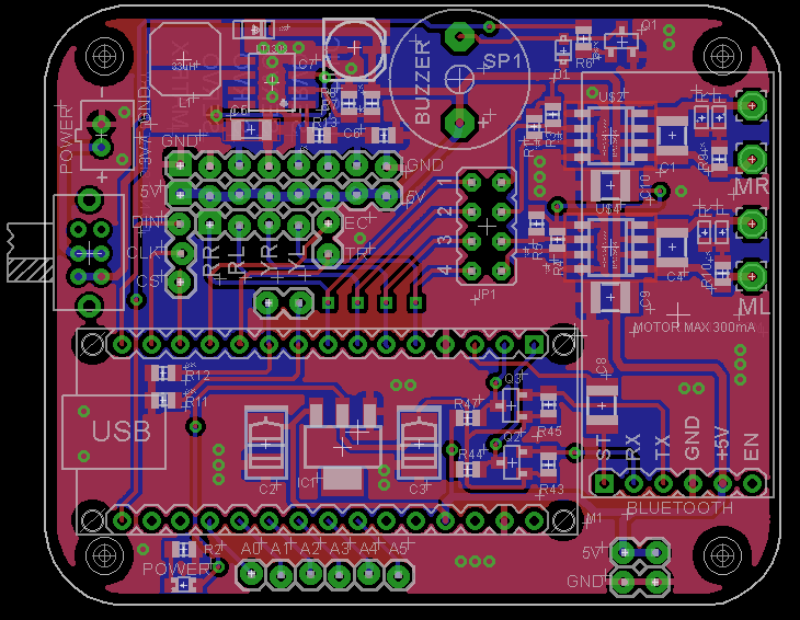
Electronic Design- Custom made PCB for Otto, (now we use 2 boards that could be replaced by one with more functions like battery, integrated buzzer and microphone)
- More sensors interactions like poking, tilting or clapping.
- Emotional aspect how can be more than just a robot?
Made with Autodesk circuits you can modify here: https://circuits.io/circuits/1749080-otto-circuit/
Shield made by Hien Pahn from STEMbot:
Shield design by Gustavo:
Shield by Jason Snow:
3.9 volt output to lipo whilst charging:
Lipo charge led went off at 4.2volt charge level Perfectly. ON/OFF switch works fine, switching various components so is not switching large currents and will last longer and is smaller in size.
ProgrammingIt is easier to program using an AVR ISP mark 2 programmer and the software AVR studio version 4 This is what I used in the pictures I suggest downloading the software and buying a programmer as all PCB's will need programming:
Olimex make this progammer I have not yet tried it as I have both but it should work.
Original avr isp mark 2 programmer Hard to find as no longer made, if you can get one it is worth your while, this is what I used
Here is a link to the one drive folder with the bootloaders, one for the Atmega 1284P and one for the Atmega 16U2. The .elf are the production files for use with AVR studio and the AVR ISP MK11 programmer.
These are the exact ones that I am using.
The Arduino IDE needs these files so that you can program the new PCB's. Please install these exactly as per the READ ME using the
How to InstallBoards Manager InstallationOnce complete, restart the Arduino IDE To use our PCB's you must select them from the tools menu in the IDE. This ensures that the Arduino Pin-Outs match our PCB's exactly so no changes to the sketches are needed.
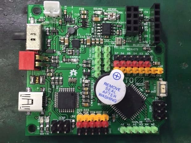
Jason design and prototype testing. Solder two pins together on small Atmega (small PCB issue to be corrected):
Check and change direction of diode D6 (manufacturing error):
Change inductor for correct value (manufacturer alternative incorrect):
Programmed both atmega chips, PCB's will accept programs from IDE over USB. I need to check Bluetooth next.
There is no way that the 3v3 regulator is working as I only get 1.8 volts out, probably because it is either faulty or has been mistaken and incorrect regulator has been sourced / supplied. I will order some replacement parts of the original specification and fit them. Hopefully they will be be here soon and I will try the Bluetooth module.
Our other pcbRemoved Wi-Fi socketRemoved the red dip switchMoved the buzzer so that a standard one can be usedAdded two more digital pins via headers.This also now uses the same dc-dc converter as my other pcb and will deliver 4amps at 5volts which is working well on my pcb.Moved Bluetooth module to pins D6 and D7







Comments
Please log in or sign up to comment.