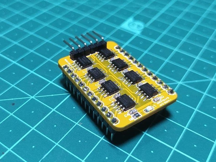
I was needed to control almost 200+ relays using one microcontroller and during research I found out that best way to do it is by using a GPIO Expander module but I wanted to have some simpler solution which should be both small and compact. Now if you worked with addressable RGB LEDs or neopixels you already know that we can control lots of such LEDs by just using one output pin.
There is a chip inside each of the LEDs which can control 3 outputs, Red, Green and Blue LED in this case. It reads the data coming from the microcontroller, set it's outputs according to the given instructions and pass the rest of the code to the next IC.
This way we can daisy chained as many of them as we want. I just wanted to impliment the same principle for any output devices in general, such as relays, to control even bigger loads. The IC used inside the neopixel LED is WS2811 which is a signal line 256 Gray level 3 channal Constant current LED drive IC. Eaxh IC can control 3 outputs but the maximum current per channel is limited to 18.5mA. Which is enough for driving an LED but not enough to drive a relay.
Luckily all relay modules come with a built in driver circuit which consist of an optocoupler and a transistor. And it only requires high or low signals to turn on and off the relay. So basically we are switching the LED inside the optocoupler to control the relays.
Keeping that in mind I designed a tiny PCB which contains 8 WS2811 IC. so we will get a total 24 outputs but as I mentioned earlier you can connect more of this ics if required. Then I head over to PCBway for manufacturing the PCB.
After assembling and adding the header pins it is ready for testing. The module is breadboard friendly so you can put it on a breadboard. First I added 12 leds to test the circuit. Now to add the ESP-01 module I used a DIY breadboard adapter. First I run a example sketch from the fastLED library, which seems to work perfectly.
Then I replaced the LEDs with relays and modified the code for the project. It is based on fastled Library. I made some changes to it so that you can easily control the individual outputs.
#define NUM_LEDS  8
#define DATA_PIN  2
You need to mention the number of ICs and the pin number it is connected to. Everything is handled by only two functions.
out.on(n);
out.off(n);
For example to turn on an output high use out.on followed by the the output number and out.off to turn it off. As simple as that. Then I added the blynk program and uploaded it to the ESP-01 module. And we are successfully able to control all these relays using only one data pin from the microcontroller.


Comments
Please log in or sign up to comment.