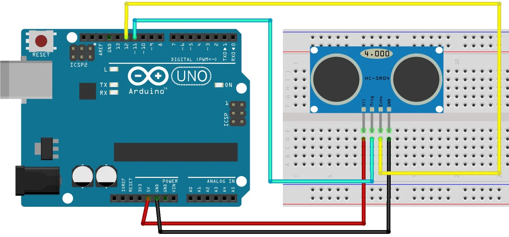
When you tried to make the ultrasonic sensor work, you probably have found that the precision of HCSR04 is very low. This project is about upgrading its measurements to the point when they are stable and accurate. If you think now that it’ll be a really tough project with lots of sophisticated methods being used, I want to say it now: it won’t. This tutorial will show a few simple tricks that should be used by everyone but unfortunately, nobody uses them. It’s time to change it!
Getting startedIf you know how hcsr04 works and used some basic code with it, you can skip this part.
How the ultrasonic sensor works.he ultrasonic sensor uses sonar to determine the distance to an object. Here’s what happens:
- The transmitter (trig pin) sends a signal: a high-frequency sound.
- When the signal finds an object, it is reflected and…
- … the transmitter (echo pin) receives it.
The time between the transmission and reception of the signal allows us to calculate the distance to an object. This is possible because we know the sound’s velocity in the air.
HC-SR04 Ultrasonic Sensor PinoutPins
- VCC: +5VDC
- Trig: Trigger (INPUT)
- Echo: Echo (OUTPUT)
- GND: GND
The main part of the code is a function that measures time after the signal on the Trigger pin to the moment when the signal on the Echo pin goes low.
digitalWrite(trigPin, LOW);
delayMicroseconds(5);
digitalWrite(trigPin, HIGH);
delayMicroseconds(10);
digitalWrite(trigPin, LOW);
// Read the signal from the sensor: a HIGH pulse whose
// duration is the time (in microseconds) from the sending
// of the ping to the reception of its echo off of an object.
pinMode(echoPin, INPUT);
duration = pulseIn(echoPin, HIGH);
//With measured time we calculate the distance in cm:
cm = (duration/2) * 0.034;
And everything seems fine! But it’s not working.
What’s wrong with standard code?After gathering some data we plotted a graph with it. It shows the time that took the sound to travel from the sensor to the obstacle at 30cm distance and backward.
As you can see it, it’s an absolute mess. You may say that it’s just the inaccuracy of the sensor but I found a solution to this. The problem is not in the sensor but in Arduino. When Arduino works it executes the code that you wrote but not only. Sometimes the processor gets a signal to freeze your code and make something else and after that, he resumes what he froze. That situation is called handling an interrupt and is very common on Arduino. The problem is that interrupt freezes our timer (PulseIn function) and thus our readings are messed up.Fixing this is quite easy. It’s only two lines in standard code:
noInterrupts();
duration = pulseIn(echoPin, HIGH);
interrupts();
Without interrupts, our readings look a way better but still, we see that some readings are 25µs higher and few are even 50µs more than normal. So why it is? Maybe this is the accuracy of the sensor? Still no.
25µs peaks.The frequency of sound in the sensor is 40 kHz and the sound wave when returning is recorded by the sensor. The sound wave is emitted for 200µs and this means that it contains 8 wave peaks. Sometimes the first returning peak isn’t loud enough to trigger the sensor.
Returning sound wave, first peak not recorded. Graphs made with osciloscope.
How to fix this?It’s not as easy as with interrupts and I don’t have an exact code to fix it. Only an idea of how that correction should work.The First idea is to take a mean of a large number of measurements but this means that we will always have higher results than real.The second option is to divide the results into two groups and calculate the mean of the lower. So first calculate the mean of all measurements and then take the average of results that were under it.
The real accuracy of HCSR04.The HCSR04 waits for the wave to return and checks once per 3µs if that’s the case. Problem is that this means that our measured time is higher than real by up to 3µs. And you won’t do anything about this without changing the sensor. But still, 3µs means 1.02mm accuracy.


_ztBMuBhMHo.jpg?auto=compress%2Cformat&w=48&h=48&fit=fill&bg=ffffff)


Comments
Please log in or sign up to comment.