Nowadays, the industry 4.0 is here and Arduino will be part of this. Arduino has also many support sources and evolves every time bit a bit. Because Arduino is the most popular and pioneer platform in DIY quick prototyping, It can be used in the industrial context with some additions to the actual technology too.
What is most related platforms in a industrial context?. The PLC (Programmable Logic Controller) started like process control systems, but through the time, they evolved. the PLC has a modular paradigm, adding more functionalities as communications which are included currently. PLCs can communicate with distributed elements through field buses.
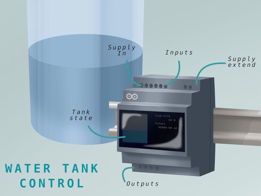
The challengeHow can include Arduino in the industry?. The main idea is construct an Arduino-based monitor for water tank level. I hope to develop a HMI based on the LOGO platform. Additionally, the design will connect with the PLC and interchange information about the tank status and possible data acquisition.
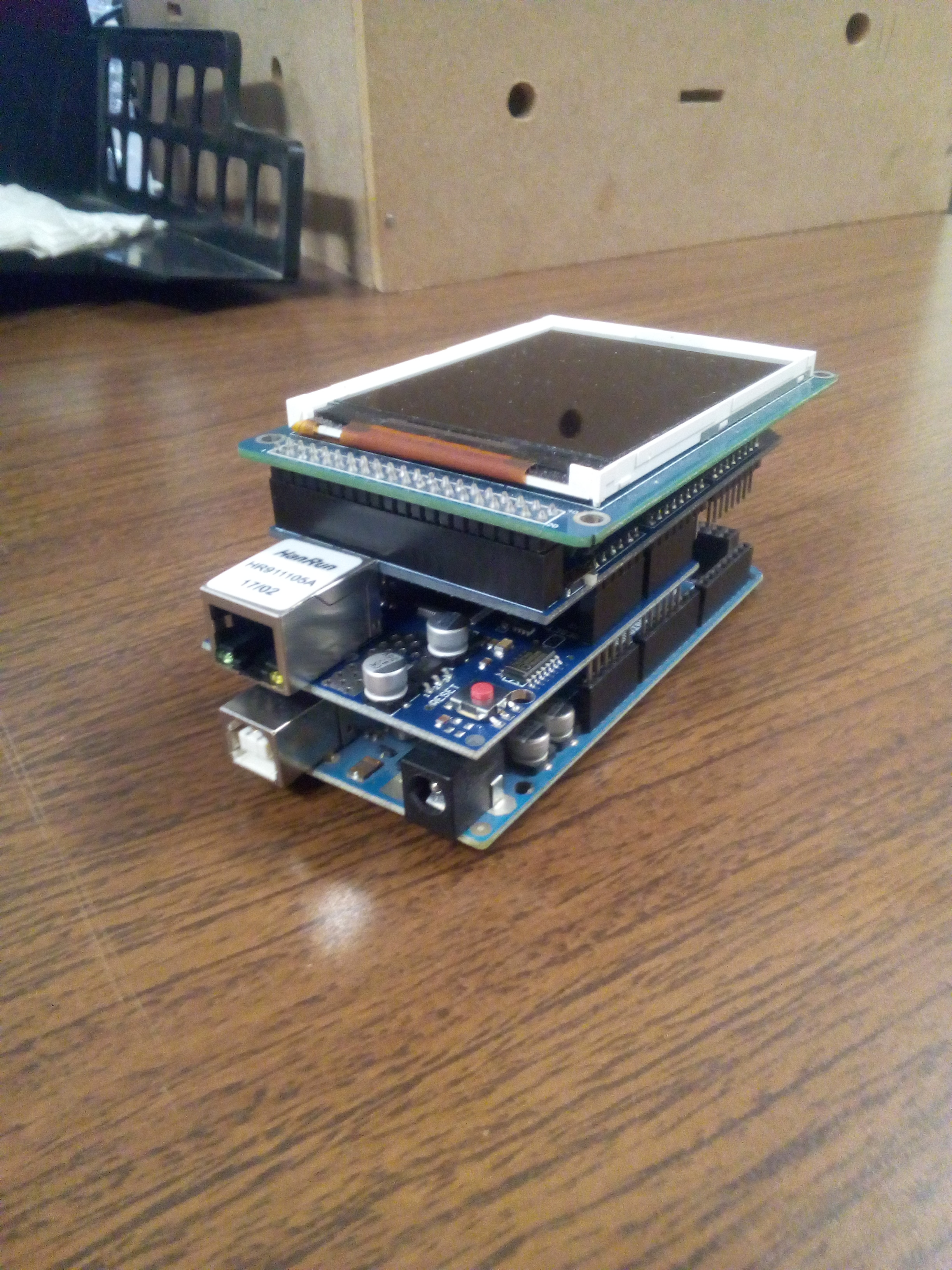
The graphical motorI started with the use of the UTFT library to create a graphical motor to show simulated tank information. According to the ISO 9241, We need accomplish at least the next points and a bit more if we want to control and interchange information:
- The application must be designed for the particular task.
- The application must report the status of the process in undestable form
- The application must adapt to the user experience
- The aplication responses must be coherent
- The aplication must be simple and easy to use
To achieve the points above, the first test is about the graphical motor, the data is represented by a predefined layout based in display's size percentages, therefore, the data size is auto-adjusted according to the display dimensions, and invariant to the orientation.
In 1979, Modicon developed the Modbus protocol in order to transmit digital signals, analog signals and registers between devices, about a Master-Slave communication. Some friends call it the Arduino of the industrial communication by its quick implementation and support of developers.
To achieve the communication, I use the Modbus library for Arduino developed by Marco Gerritse. Because the percentage of the tank can be treated as analog signal, the program uses the Holding Register (HR) 40001 to store the value of the tank. The HR40001 should be used in the PLC to reference the tank value.
PLC programThe selected PLC was the LOGO 8 of Siemens by the low cost and its capabilities for automation and communication in wired network. A small program, showed in schematic format on the next figure, is sufficient to map a network variable and show the data in the LOGO display. Remember, the default port of the Modbus communication is the 502.
- NAI2 describes a Network Analog Input for the HR40001, We need present that a communication profiled needs be configured.
- M25 is mapping the white backlight of the Logo PLC display
- M29 is mapping the red backlight of the Logo PLC display
- B001 negates the threshold status to show when the tank is next to the maxium
- B002 configures a message in the PLC display, it will show the value of the tank.
- B003 represents an Analog Thresold configured to On state and Off state with the values 85 and 75 respectively.
- M1 is used like dummy output to avoid a compiling error
Why I use the HR? Because the HR has an analog nature, it is perfect to share values different to ON/OFF status. The display text, in the B002 block, is configured with the next characteristics.
Thanks to the analog threshold, we can map the HR40001 value and add this to the display. In addition to the numeric value, we can add a progress bar format visualization.
For the network PLC profile, Arduino, PLC and the PC must be in the same network in order to program and test the project. By default, our computer is added to the network; the PLC and the Arduino must be added like a LOGO!8 FS4 and Modbus-compatible devices respectively. The default address for LOGO is the 192.168.0.10, the addres default for the arduino ethernet shield is 192.168.0.12 and can be modified by code. This sees like the next figure
If you want to avoid software and harware version problems you can acquire the LOGO! 8 Starter Kit 12/24RCE and see that the versión of hardware and software be 8.1 at least. After program the Arduino and PLC, We can run a live simulation to avoid go to the PLC display.
In the real device we must see the same behavior
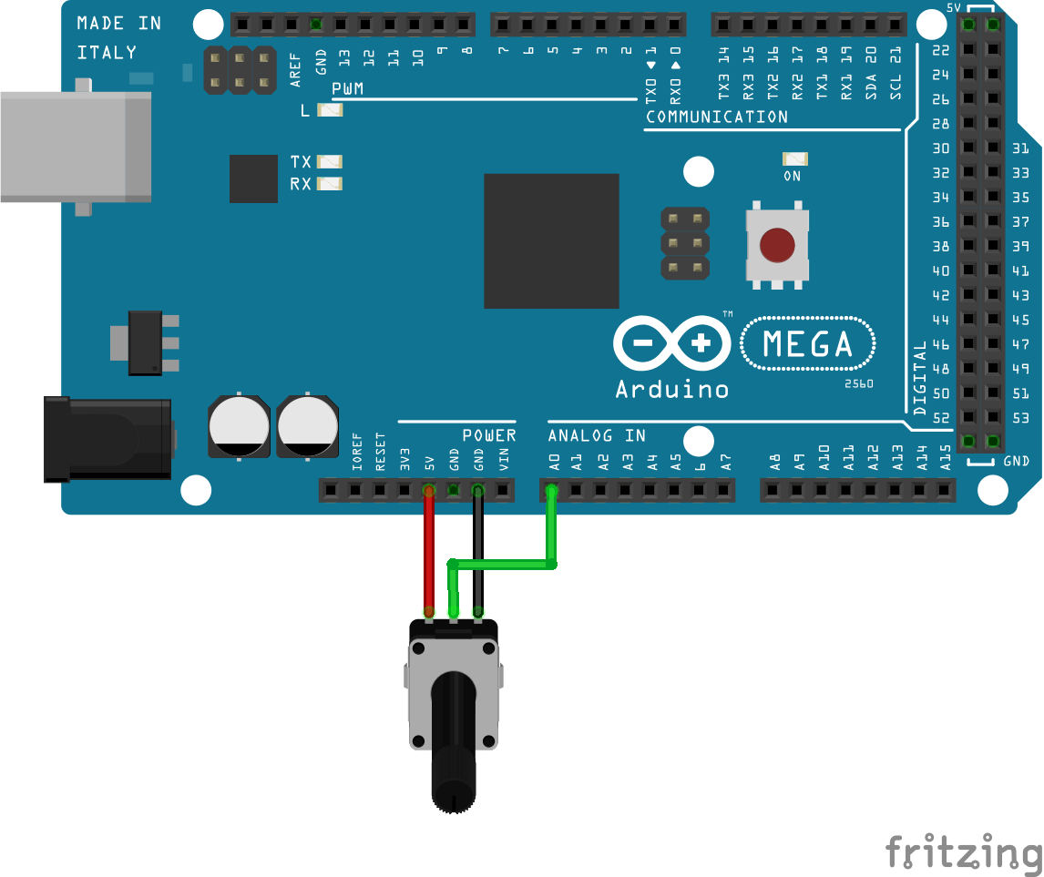
To acquire the tank status we can use an analog level sensor with 0-5V output or simulate with the use of a potentiometer in the analog input 0 of the arduino. Moreover, a coupled signal of an industrial standard sensor also can be used.
Fully AssembledThe final assembly sees like the next figure, we can observe the Arduino water tank monitor next to the LOGO PLC and the data sharing through the network,
The data is shared between the devices and we can compare the displays with their code behavior.


_wzec989qrF.jpg?auto=compress%2Cformat&w=48&h=48&fit=fill&bg=ffffff)


Comments
Please log in or sign up to comment.