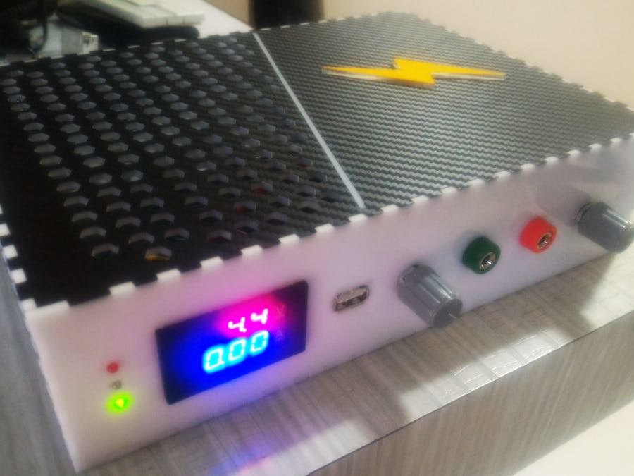
Every engineer needs at least one bench power supply in his house. I agree one can get the power supply directly from the store, but they are costly and some are ugly in terms of design too.
We all need to make sure that the power supply represents the person who is using it, whether it is a student or an engineer or an hobbyist, this is my personal opinion.
Let's make the case creative and include features of a high end model. Lets modularize it so that in future we can modify it. This is a single channel power supply.
I was frustrated with using so many power adapters such as 9V 2A, 12V 1A and so on. This created the mess of connections. I would need a DC DC buck regulator and always constantly checking voltage before powering any circuit, which wasted my time.
There are many types of buck regulators available in market and hooking up wires every now and then took precious time and most importantly this thing made my table really messy. With ESP8266 WiFi module, things got worse. As ESP8266 needed 3.3V with current more than that of an Arduino, it was no good powering it from Arduino.
Specifications- Input: 220-240V AC
- Output: 1.3v to 19.2v, 3A with three LEDs to indicate constant current, full charge indicator, charging indicator. Two binding posts and one USB connector as O/P.
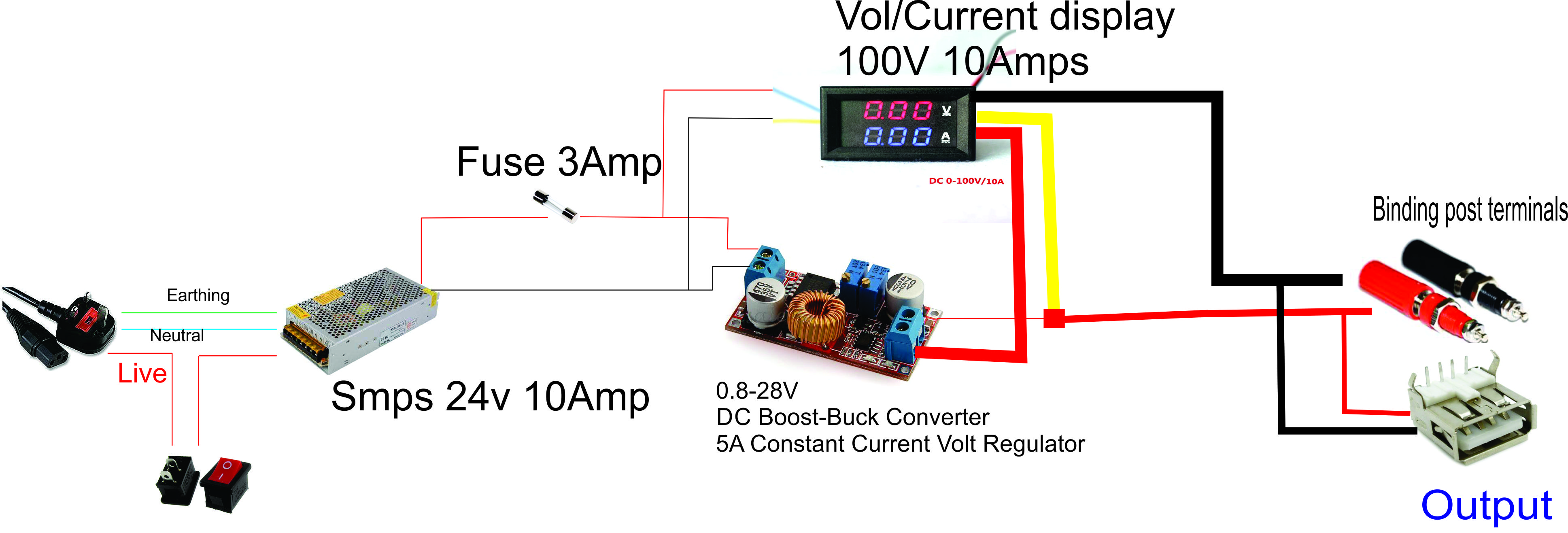
Note: The SMPS that I am using provides 24V/10Amps but 10 Amps is a lot more than I need. So, I have limited the current down to 3 Amps with a fuse that can be replaced in the future if more current is needed.
Case design and buildIt took me some time to come up with the design of the power supply and what material to be used.
In the past I worked only on acrylic laser cutting so that's why I choose acrylic. But aluminium would be a better choice to make the power supply case. It was a risk to choose acrylic but I went for it.
I thought of aluminium as top part and wanted to add curves in it. But I was not experienced whatsoever in CNC and how to achieve this shape in the end, I settled for vinyl.
You will also need to cut holes for the AC power connector unless you can modify the Corel Draw file to align holes perfectly.
- I have used two software's to make that case. One is Corel Draw and another is Makercase that is online to make Finger slots.
- You will need to check the USB A dimensions and AC power connector I did not have a Vernier Caliper to do it accurately. My friend in laser cutting made two to three cuts for perfect fit.
- For top panel sticker I choose carbon fiber material instead of that image and with vinyl cutting, I cut out that pattern.
- You will need to use Araldite to stick all sides. Don't stick the top panel, make sure it is open, just in case in future, to modify your power supply.
Verify all the wires thrice and check the connections as you will be using AC mains. Also use heat shrink insulation tube to cover all wires. So that no two wires comes into connect because of soldering. This is a very important step to ensure you do it and then move to other steps.
You will see three LEDs on the DC DC buck. Desolder the SMD LEDs and solder the wires for three LEDs that are placed on the case.
Desolder the potentiometer on the buck and solder the wires to the pot on the case. If the shaft of pot is too big make the hole bigger with a Dremel tool.
ConclusionYou did it! Now you have successfully built your own lab bench power supply that has constant voltage and constant current mode, no more use of adapters and buck buck regulators.
Be safe and modify the bench power supply if you need more current. Use 10 Amps DC DC buck and use 10 Amps fuse with it.


Comments
Please log in or sign up to comment.