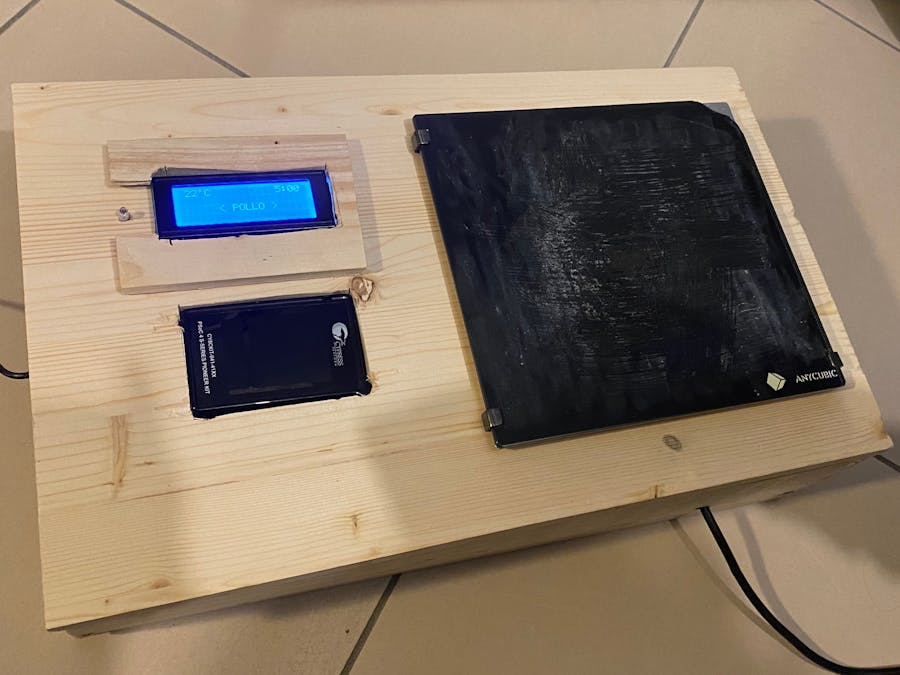
Tidying up my closet, I found this heatbed from my old 3d printer and I realized that something beautiful could be made with it. And here is the perfect idea. A small smart kitchen controlled by the CY8CKIT-041-41XX kit.
The goal is to create a Smart-Kitchen whose temperature can be controlled by the Psoc Board's CapSensor. Furthermore, the device should have some culinary recipes thus allowing the user to save time and optimize the cooking temperature and time.
The idea consists of a heatbed that heats up based on the temperature chosen by the user. This can check on an LCD all the necessary information; the current temperature, the various possible recipes and the cooking time once a recipe has been started.
First of all I recovered all the components necessary for the realization.
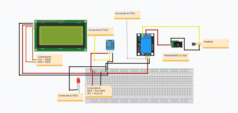
I used a 20x4 I2C LCD to display the current temperature of the heatbed (detected by the DHT11), and to display the various possible recipes. To heat the surface I used a 12V 30A transformer (also present in my printer). And to control the ignition of the heatbed I used a Relè module 12V 30A. I also used a small red LED as a status LED which I then added to the final structure.
To detect the temperature you can use an NTC that is pre-inserted into the heatbed. Mine unfortunately broke so I opted for this module.The Hardware Connection
I connected all the components following this scheme:
Note that:
DHT (Data) -> P2[2]
Relè -> P2[5]
LED-> P2[5]
LCD_SDA -> P0[5]
LCD_SCL -> P0[4]
CapSensor connected to Psoc
The CodeTo program the device I used the Psoc Creator environment.
The Design file consists of 4 main components:
- A RTC (Real Time Clock) which allows you to obtain the current time, which is then used to control the cooking time.
- A Capsense which allows the user to interface with the device. This consists of two buttons (used to raise and lower the required temperature) and a trackpad (used to choose between the various recipes).
- A CharLCD I2C which is a custom component available at this <link<<<<<. This component combined with an I2C master allows you to quickly control the 20x4 I2C LCD.
- A I2C Master Component which is attached to CharLCD I2C.
Then there are the two Digital output pins (LED and Relay) and the Digital input pin (for the DHT11).
Now let's see in detail some fundamental functions for the system.
DhtRead()
int DHTread() //Read function of Temperature and Humidity (DHT11)
{

    uint8 IState;
   IState=CyEnterCriticalSection();
   uint8 bits[5];
	uint8 cnt = 7;
	uint8 idx = 0;
   int   calc=0;
   int   timeout=0;
   for (i=0; i< 5; i++)
       bits[i] = 0;
   DHT_Write(0u);
   CyDelay(19);
   DHT_Write(1u);
   while(DHT_Read()==1)
   {
       timeout++;
       if(timeout>500)
           goto r99;  //DHT error function
   }
   while(DHT_Read()==0)
   {
       timeout++;
       if(timeout>500)
           goto r99; //DHT error function
   }
   calc=timeout;
   timeout=0;
   while(DHT_Read()==1);
   for (i=0; i<40; i++)
	{
       timeout=0;
       while(DHT_Read()==0);
       while(DHT_Read()==1)
           timeout++;
       //Data acquiring point
       if ((timeout) > (calc/2))
           bits[idx] |= (1 << cnt);
       if (cnt == 0)   // next byte?
   	{
   		cnt = 7;    // restart at MSB
   		idx++;      // next byte!
   	}
   	else cnt--;
   }
   humidity    = bits[0];
   temperature = bits[2];
   CyExitCriticalSection(IState);
   CyDelay(1);
   return 0;
   r99:    //Goto label for error in DHT reading
       humidity    = 99;
     //  temperature = 99;
       CyExitCriticalSection(IState);
       return 99;
}
I use this function that allows you to read the Dht Pin values and convert them into the detected temperature (°C). If you want there is this excellent article that explains how to connect a DHT11 to a Psoc board.
pagevoid()
int pagevoid(){
       DHTread();
     CharLCD_ClearDisplay();
        sprintf(mss,"%i'C ",temperature);
        if ( temperature<tempR){
           sprintf(msstr,"Rq  %i'C ",tempR);
          CharLCD_PosPrintString(0u,12u,msstr);
        } else{
             CharLCD_PosPrintString(0u,13u,"       ");
        }

        CharLCD_PosPrintString(0u,1u,mss); //Y-X

        if (page == 1){
        CharLCD_PosPrintString(2u,6u,"< POLLO >");
        } else if (page==2){
          CharLCD_PosPrintString(2u,6u,"< THE' >");
        }else if (page==3){
             CharLCD_PosPrintString(2u,6u,"< PASTA >");
        }


return 99;
}
This is a function that allows you to print on the screen the temperature detected and the one requested (when necessary), the various recipes based on the page where the user is located (which can be switched thanks to the Trackpad gesture) and the cooking time when starting a prescription.
setrecipe()
int setrecipe(){ //Here thre are the recipes
     if (page == 1){//Pollo
           tempR =74;
        timecook=22; //22
          timebefore=RTC_GetMinutes(RTC_GetTime());
       // alarm(1320);//Set the timer for 12m for the chicken
        } else if (page==2){//THE'
         timecook=12;
         tempR = 100;
    timebefore=RTC_GetMinutes(RTC_GetTime());
       // alarm(720); //Set the timer for 12m for the water

        }else if (page==3){//Pasta
        tempR = 100;
        timecook=20;
         timebefore=RTC_GetMinutes(RTC_GetTime());
       // alarm(1200); //Set the timer for 12m for the water +8m for the pasta

        }
        return 99;
}
In this void we give all the information about the recipes, cooking time and temperature. I loaded 3 as a demo but if you want you can load many more.
timecontroll()
void timecontroll()
{
     timeatt = RTC_GetMinutes(RTC_GetTime()); //Actual-Timeme
    uint32 timetot = timeatt-timebefore;
    if (timecook !=0){
    if (timecook==timetot){
        takefood();
        timecook = 0;
      }
        itoa(timetot,msstest,10);
        CharLCD_PosPrintString(3u,17u,msstest);
    }

}
This is a fundamental function that allows you to correctly set the cooking time. Thanks to the RTC module, it compares the current time with the one recorded at the beginning of the recipe. This function is called constantly in the main void.
In the main void there is this part of code that is used to check the print bed and its temperature. This code compares the current temperature with the requested one and allows you to heat the plate as much as you want.
if(tempR!=0){
            if (temperature <tempR){
             rag = 0;
             Rele_Write(1);
             Led_State_Write(1);


        }else{

            Rele_Write(0);
             Led_State_Write(0);
             rag =1;
         }
        }
In the main void there is also this piece of code that decode the gestures detected by the capsense and move between the pages to change the recipe.
if(CapSense_NOT_BUSY == CapSense_IsBusy())
        {
            // Process all widgets
            CapSense_ProcessAllWidgets();

            // Scan result verification


            if (CapSense_IsWidgetActive(CapSense_BUTTON0_WDGT_ID)) //Button +
            {
               Led_State_Write(1); // LED on
                tempR ++; //Increases the required temperature
                CharLCD_PosPrintString(2u,3u,"+");

            }else if(CapSense_IsWidgetActive(CapSense_BUTTON1_WDGT_ID)) { // Button -
                     tempR --;//decreases  the required temperature
                     CharLCD_PosPrintString(2u,3u,"-");

              //  Led_State_1_Write(1);    // LED off
            } else{
                // Led_State_1_Write(0);
                // Led_State_Write(0);
                CharLCD_PosPrintString(2u,3u," ");
            }

            detectedGesture = CapSense_DecodeWidgetGestures(CapSense_LINEARSLIDER0_WDGT_ID);

             switch(detectedGesture){
            case CapSense_ONE_FINGER_FLICK_RIGHT:
                if(page<maxpage){
               page++;
                } else{
                   page = 1;
                }
                break;
            case CapSense_ONE_FINGER_SINGLE_CLICK:
               setrecipe();
                  CharLCD_PosPrintString(3u,6u,"                   "); //Clear the row
                 CharLCD_PosPrintString(3u,6u,"OK");
                break;
            case CapSense_ONE_FINGER_FLICK_LEFT:
                if(page!=1){
               page--;
                } else{
                   page = 3;
                }

                break;
            }


            // Start next scan
            CapSense_ScanAllWidgets();
}To complete the project I built a wooden structure that could contain all the components.
I used 2 40x30cm rectangular pieces as base and lid, two 30x10cm for the smaller sides and finally 40x10cm for the smaller sides. I used this simple 3d model made in Tinkercad to guide me in the construction of the structure.
As can be seen in the upper part there are 4 holes of 4.5mm which allow the plate to slide inside the structure. Below the plate is the DHT11 sensor also hooked with a 4.5mm screw.
Next to the plate is positioned LCD with the Capsense underneath. Here too I drilled a 10x9cm rectangle for the LCD, also covering it with a small detail that highlights the LED when turned on. For the CapSense I used the same technique.
Then I drilled a larger side of the box to pass the power cord of the transformer, and I positioned all the components as seen in the photo.
The result is really nice even though it was all made at home.
The first version of the device is finished. I will certainly continue working on this project, perhaps replacing the LCD screen with an Oled with pre-inserted Touch, and adding many other recipes. For sure the CY8CKIT-041-41XX is a perfect board for this project, especially for the pre-installed Capsense and RTC.
This is a small demonstration video.


_t9PF3orMPd.png?auto=compress%2Cformat&w=40&h=40&fit=fillmax&bg=fff&dpr=2)


Comments
Please log in or sign up to comment.