Do you ever struggle to close your curtains because of the arrangement of your furniture? Do you ever want a little more automation in your house just for convenience sake? Say no more, because we have the solution for you. This is C and P's Automated Blind system. This automated system consists of three major components being mechanical, electrical, and computer.
MechanicalThe mechanical portion of this project is essentially the hardware of the design. This includes parts such as pillow block bearings, metal rod, pulley & belt system, curtain holder, curtain rings, and fishing wire.
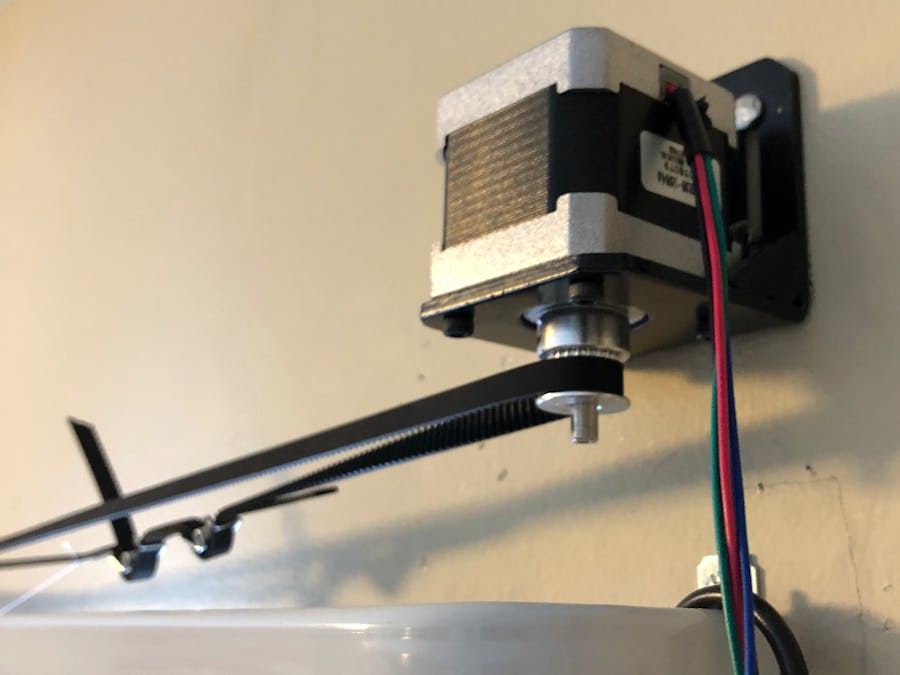
The biggest mechanical issue of the project was figuring out how the pulley would operate. One side of the design is driven by the stepper motor, but the other side would also need a geared pulley. To solve this, we used two bearings and connected a rod thru them. On this rod, is the geared pulley which allows for more precise mechanical movement. The bearings and rod also steady the jig, that way it operates purely on one degree of freedom. Commanding the stepper motor moved the belt, side of the belt going one direction, the other going in the other direction. The curtain's were then mounted right below the belt. These curtains were only being held on by metal rods, and can easy be opened and closed with your hands. A fishing wire is attached to the belt, and the last ring of the curtain. Once attached tightly, if the belt is moved, it will add tension to the fishing wire, and pull the curtain as well. The next step is the control of the stepper motor through our electrical components.
ElectricalThe electrical component consisted of two particles photons, sound sensor, LED, a stepper motor, and a stepper motor driver.
Photon Driving the Stepper(Particle1)
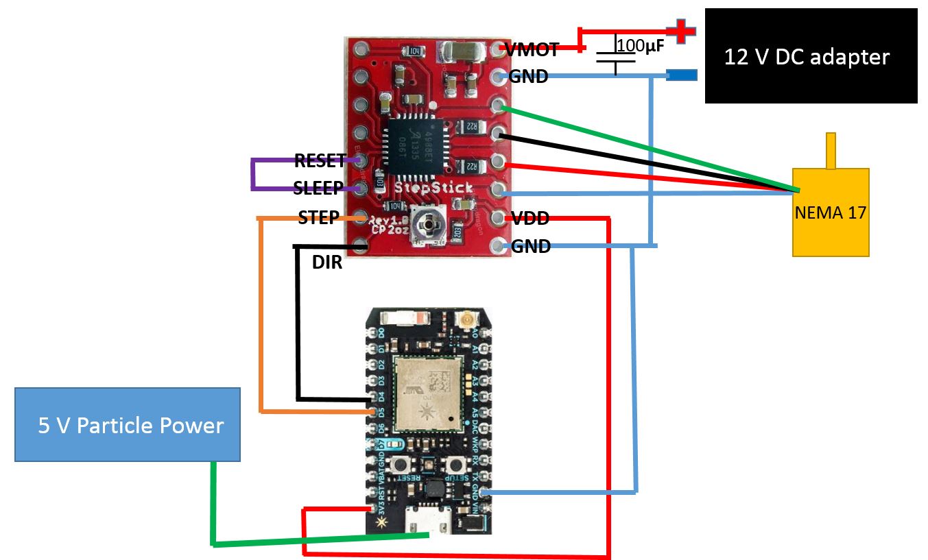
The a4988 stepper motor driver is a must for this portion of the projects success. Controlling the stepper motor becomes a breeze once everything is equipped correctly. The driver requires 8-32 V of DC power, that is supplied through a 12 V DC adapter. A barrel jack connected to the end of the adapter so two wires can go straight into the bread board to supply the 12 volts.
Those 12 V are then wired to the VMOT pin of the driver. A 100 μF capacitor was placed in parallel with the +12V and ground. This is done to protect the driver from the high frequency voltages going into the VMOT. Even though a DC power source is used, the transient period from 0 V to 12 V when the adapter plugs in creates an AC component for that short period of time. The capacitor in parallel with the power from the adapter acts as a low pass filter, only allowing low frequency signals into the driver during the transient period, and after a long period of time it acts as a short. The 3V3 pin of the photon must be connected to the VDD of the driver to act as a reference voltage. The rest and sleep pins of the driver must be wired together. All the grounds must be tied ( 12 V adapter, particle, and driver). Wires of the stepper motor are also placed into the driver in A and B pins. Finally two digital pins of the particle must be placed in the STEP and DIR pins of the driver. Now the stepper motor can be controlled with digital writes from those pins of the particle.
Photon Listening(Particle2)
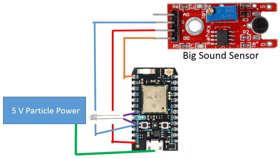
The "Big Sound" sensor has a simple wiring process. The V+ pin must be connected to the 3V3 pin of the particle, and the ground of the sensor and particle must be connected. A digital read is taken of the DO pin on the sound sensor.
Once this read is triggered, an LED is lit up on particle 2 so that we know the sensor was triggered. And a publish is made to Particle 1, telling it to either open, or close the curtains.
Particle wed IDE was used to write everything.
Particle1
This particle is in charge of driving the motor. The electrical portion connected a digital pin to STEP and another pin to DIR. The DIR pin is used by writing a HIGH to it or a LOW, one will rotate the motor in one direction, the other the opposite. The STEP pin requires a HIGH then a LOW, to make the motor move one single step. A for loop is used for our code, of a HIGH then LOW with a 1 ms delay between them. The for loop will run for the inputted amount of steps, the NEMA 17 stepper motor used has 200 steps per revolution. This means if I input 200 steps, the motor will move one full rotation, changing the delay between the HIGH and LOW writes will change the angular speed of the motor. It was found that a 1 ms delay was the fastest the motor when it was pulling the curtain. The motor was rotating a pulley that had a half inch diameter. Conversions were made calculate exactly how many steps would be needed to move the pulley an inputted distance in millimeters.
Steps=LinearDistance*(200/42.34866)
Our conversion came out almost perfect, it it amazing how well accurate the stepper motors are.
Once a perfect distance was found that would move the curtains the desired distance, it was kept.
This particle was receiving its commands from particle 2. The code has two functions in it, one to open the curtains, one to close. They are the same functions, the only difference is the direction of the stepper motor. The functions are called on by particle 2 from a particle.subscribe in the void setup.
Particle2
This particle was assigned to be sending the message to particle on when to move, and if that move should be to open or close. The sensor was read through a digital read from the D0 pin of the "Big Sound". This pin constantly sends out a high, except when it hears something, then it sends out a LOW. Particle 2 is programmed in a void loop where it is always taking a digital read of the sound sensor. When this pin reads a low it will go inside of the first if statement where it gives the command to open or close the curtains.
Two variables called "Position" and "moved" are inputted into the logic to differentiate between if it should send a command to open the curtains or to close the curtains.
Using particle.function would call particle 1 to either perform its function to open or close the curtains.


_3u05Tpwasz.png?auto=compress%2Cformat&w=40&h=40&fit=fillmax&bg=fff&dpr=2)
Comments
Please log in or sign up to comment.