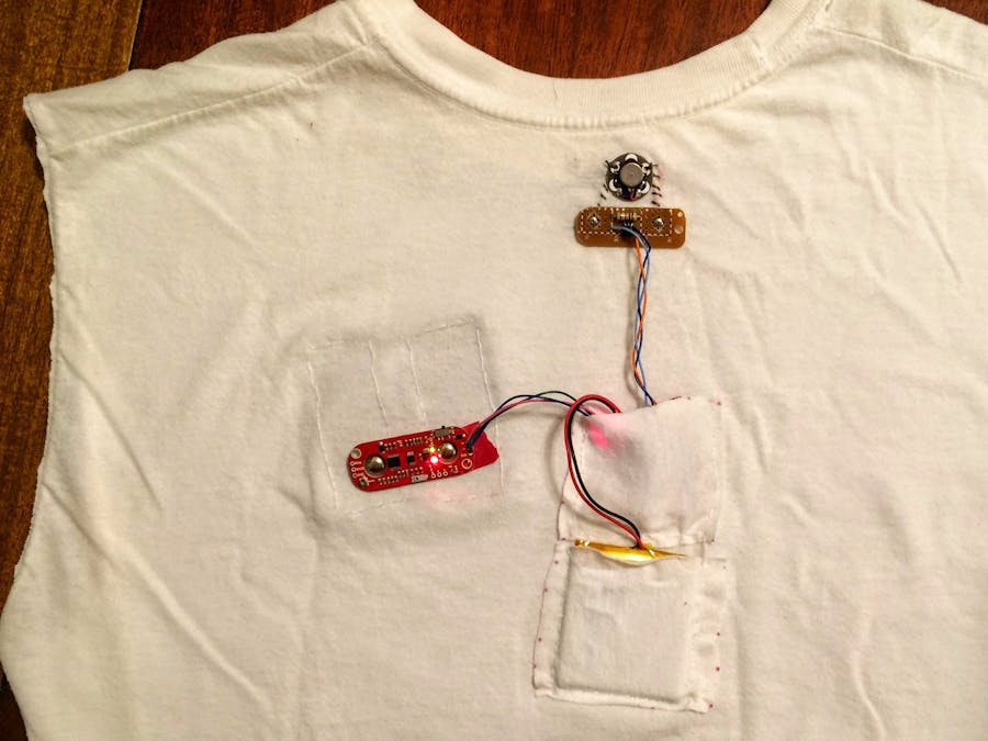
I have back pain. It seems to relate to my terrible posture and weak core muscles. This device detects superficial back muscle activity and notifies me when I slouch my shoulders. The goal is to build a good habit instead of becoming dependent on a gizmo.
Plan A: Detect abdominal activity that correlates to bad posture. I asked a physical therapist to help me with sensor placement. He said the relevant muscles are not superficial (near the surface) and sensing them requires sub-dermal probes. Since I'm not willing to walk around with needles sticking into my belly all day, plan A is officially no good.
The physical therapist pointed out some muscles that affect upper back posture are superficial.
Plan B: The sensor will read the lower portion a trapezius muscle. When detecting shoulder slouching, the controller can notify the user.
I am not a medical expert. I make no guarantees of this device improving anyone's health. If you use this electronic thing on yourself or anyone else, you do so at your own risk.
Key ComponentsThe MyoWare Muscle Sensor provides the biometric data about me to the Blynk Board for control and reporting.
The notification comes from the Lilypad Vibe Board. Many people suggested the notification should be an electric shock. One even suggested it make embarrassing body noises. I stuck to my guns on this one.
Since sticky EMG pads are not desirable to wear every day, the muscle sensor is connected to conductive fabric that rests against my skin. I expect the breathability will prevent irritation, but time will tell.
Power comes from a 2000 mAh LiPo battery. The Blynk Board's built in battery charger makes this super convenient.
While testing the vibrator, something seemed wrong. The vibrator didn't have any force. Its notifications would go unnoticed. I measured the current drawn by the Vibe Board when connected directly to the battery: ~60mA. It wants 5 times too much current for a GPIO pin of the ESP8266. This project needs an external board to drive the vibrator.
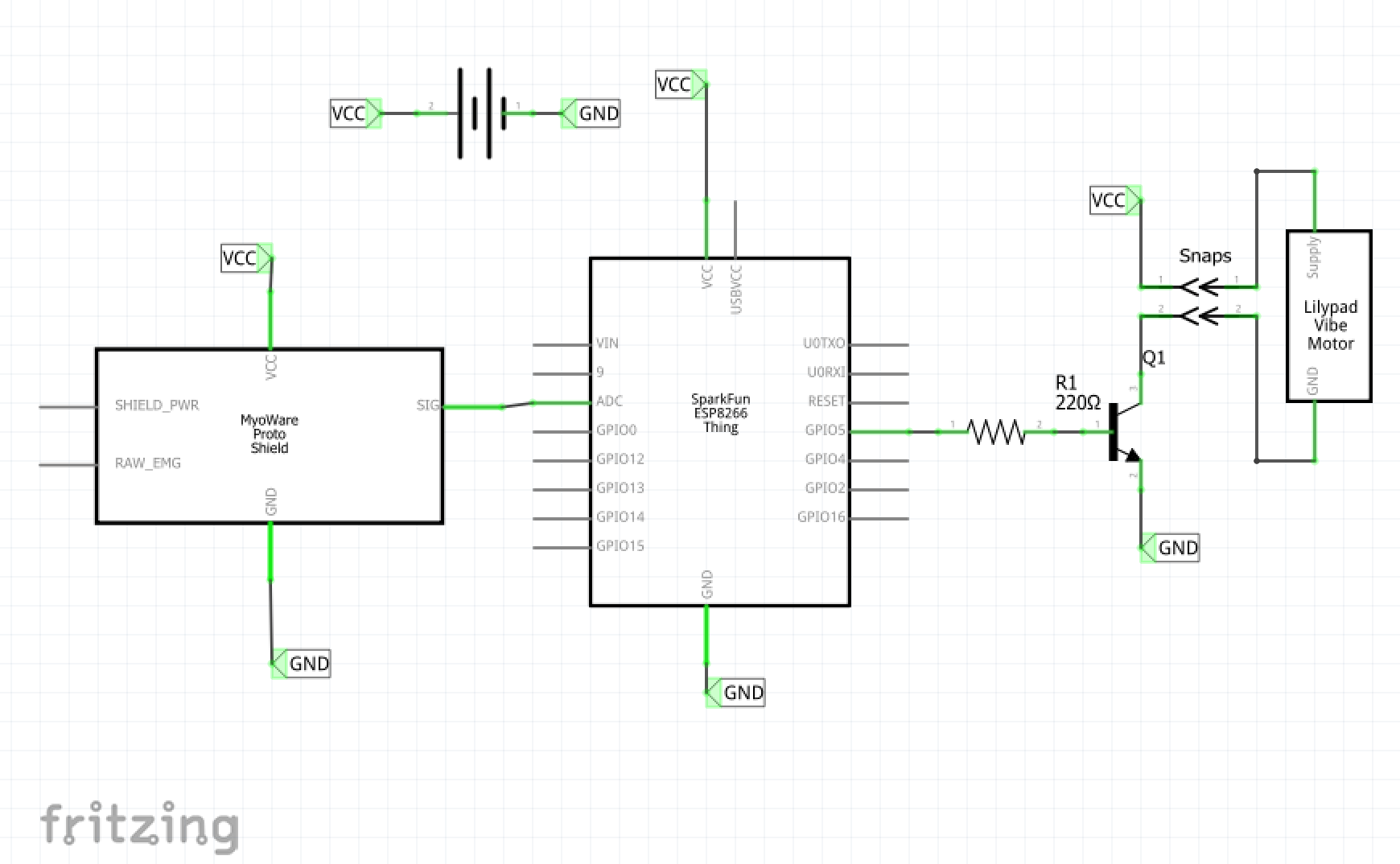
The vibrator driver board is just a transistor, resistor, and two snaps like the muscle sensor. Mine is built on a generic prototyping circuit board. The transistor does the switching, while the resistor brings the base-emitter current into acceptable limits. This transistor has a voltage drop of 0.7V, so the base-emitter voltage is 2.6V. A resistor value of 1k ohms alone limits the current to 2.6mA at that voltage. Since pin 5 of the Blynk Board connects to the base, the current across that pin is safe. The measured current across to the Vibe Board is about 30mA. It's less than optimal but still produces a strong result.
AssemblyStep 1: Solder 3 wires from the Blynk Board to the muscle sensor. Ground and 3.3v are easy to identify. The third wire connects the "SIG" output of the sensor to the "ADC" input of the Blynk Board. This output gives an analog signal to indicate the amount of muscle activity.
Step 2: Build a vibrator driver board. One snap is left to stand alone, and the other connects to the collector pin of the transistor. The resistor connects to the transistor's base. Leave a means of soldering wires to the standalone snap, the free end of the resistor, and the transistor's emitter.
Step 3: Connect the vibrator driver board. From the Blynk Board, connect 3.3V to the standalone snap, GND to the transistor's emitter, and pin 5 (or any GPIO pin) to the open end of the resistor. Pin 5 is connected to a blue LED which I suspect will prove useful for troubleshooting.
Step 4: Cut sleeves from shirt. Save the material, it will form the pockets.
Step 5: Place sensor pads. I put on the shirt inside out and my wife pinned the conductive fabric where she estimated the muscles lay. We pulled up the muscle image above and she picked a very effective placement. I also coached her based on what the MyoWare documentation says about sensor placement.
I'm right-handed, so I want the sensors placed on the left to indicate posture, not me moving the computer mouse. With the shirt inside out, she pinned the fabric to the right side. Turing it right side out again switches them back to the left.
Step6: Sew. I started by sewing the sensor pads to the t-shirt. It's kinda tricky to attach non-stretch fabric to a knit t-shirt. That's all for inside the shirt. Everything else is sewn to the outside.
The sensor snaps are conveniently placed at the appropriate distance, so just sew the the snaps directly to the sensor pads with conductive thread. A little more conductive thread for the vibe board and its snaps. Place this on the spine for maximum annoyance.
The pockets were cut from the sleeve. After snapping the circuit onto the garment, lay out the Blynk Board and battery in their final location and pin the pocket scraps to the shirt. Place them over the spine for comfortable weight distribution.
- The whole time, I gambled with omitting the reference wire from the MyoWare sensor. Without it, the sensor still picks up a valid reading. I'm certain the engineers that designed this knew what they were doing, so the reference wire would very likely show improvement in the signal.
- Sensor placement worked well without adjustment. Near the edge of the scapula keeps contact with the skin and centers the sensor over the muscle belly.
- Sensor gain is quite low. I started with higher gain, but the positive result occurred too often.
It would be super cool to make this using only Blynk, but the automation needs a little more code running on the microcontroller. Blynk, however, provides an awesome platform for settings and reporting.
This project is programmed by the Arduino IDE, but the board is not Arduino. Since this is a SparkFun product, I followed their guides to set up the environment.
The logic is pretty simple:
- Get threshold and timeLimit from the Blynk app for use in the code.
- Loops checks sensor and time elapsed
- If the sensor reading is above threshold, disable vibe and reset timer
- Else, if the elapsed time is greater than the timeLimit, start annoying.
- Else, do nothing
There are no delay() functions in the code because they interfere with Blynk. Instead, elapsed time is compared to a desired maximum. Blink without delay


_3u05Tpwasz.png?auto=compress%2Cformat&w=40&h=40&fit=fillmax&bg=fff&dpr=2)


Comments
Please log in or sign up to comment.