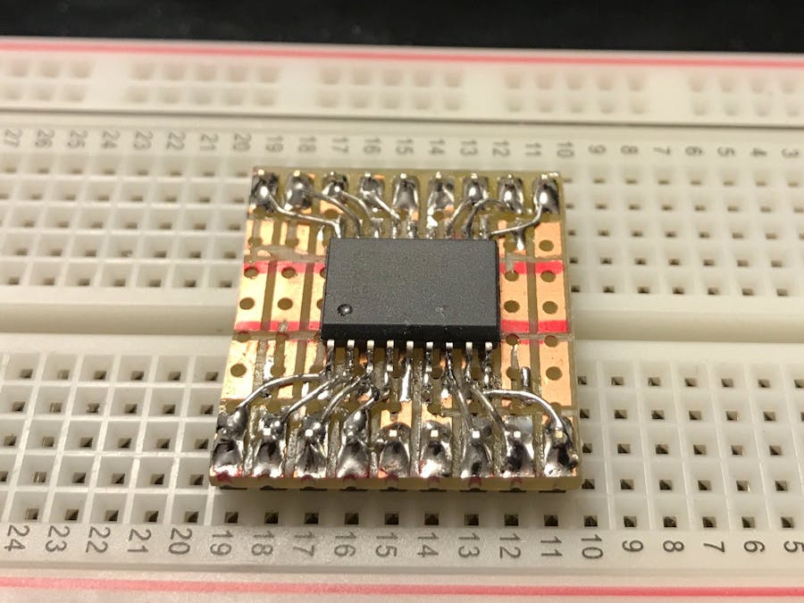
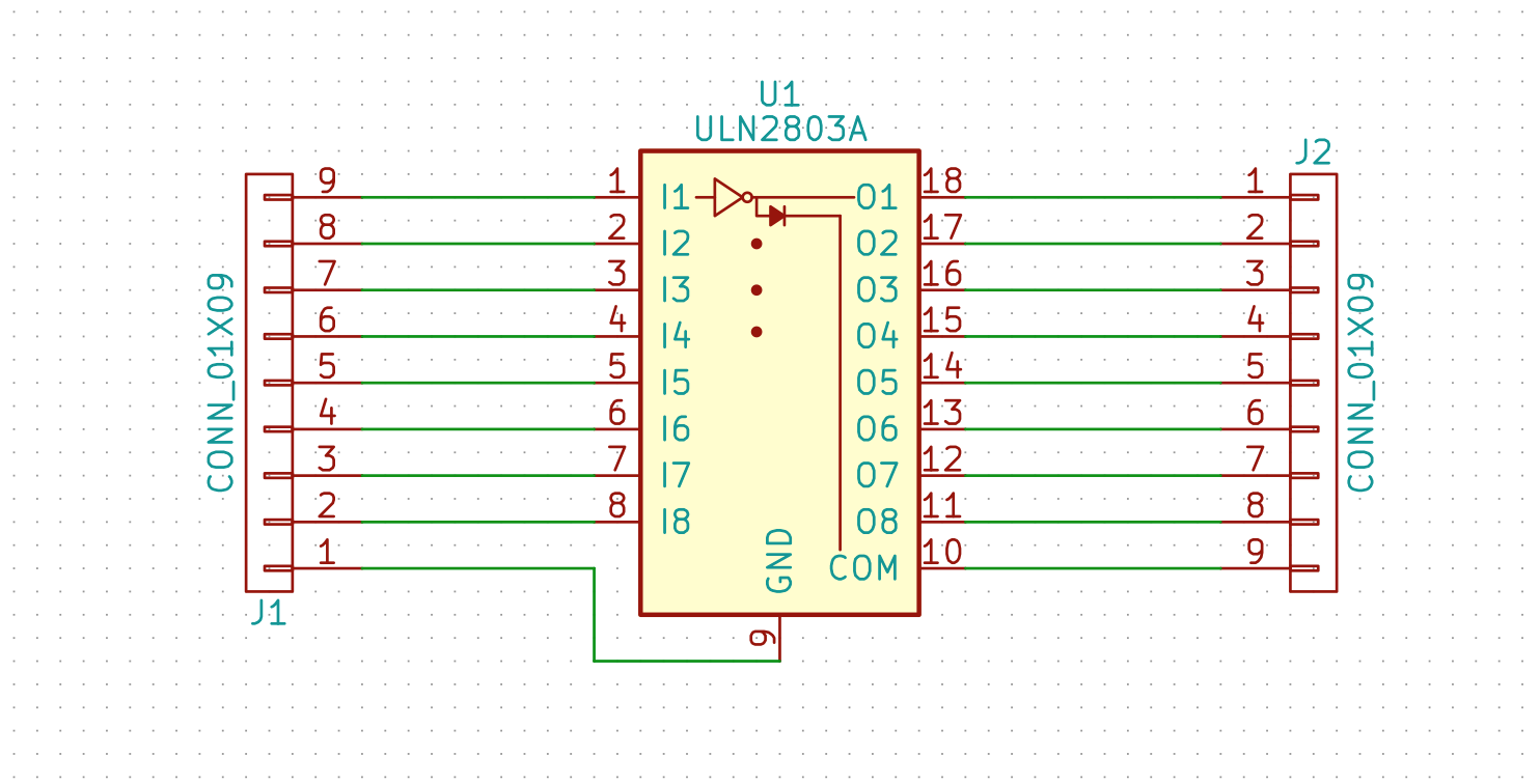
This is a simple breakout board. I bought 3 transistor array chips with the intent to use two in a custom PCB. Since that will be my first PCB, I want to examine all my assumptions before etching the wrong traces. This breakout was a simple way to test the transistor array with a relay and an Arduino.
The chipThis chip is an array of 8 darlington transistor pairs with flyback diodes and all the correct resistors for 3.3 - 5V logic. It's an easy way to turn your 40mA GPIO pins into an array of 500MA 60V pins. The channels can be connected in parallel for greater currents. The max for the whole box is 2.5A. With a common emitter, each channel makes/breaks the connection to ground.
I plan for this chip to drive relays on a custom Arduino shield, so watch out for that project.
Test alignmentI set the SOIC chip on some perfboard I had laying around to see if the pins line up in any meaningful way, and I was pleased to find they do.
I cut an appropriate amount of the board away and began to solder the chip to some pin headers.
The traces needed some cutting, so I used a rotary tool with cutting wheel to remove the copper and make a nice gap between traces.
- I started by cutting all the way across to break the two sides apart.
- Next, I split the rails into 2.
- Last, I separated the SMD pads from the pin header pads.
This was a quick and easy way to separate things, but with a little bit of hindsight, I would have left copper on there a bit more strategically and run wires under the board to make soldering easier.
I then chopped off the long leads of some capacitors and made jumping traces. (Maybe I just made up the phrase "jumping traces". Air gaps make the insulators I put the pins into a breadboard while soldering because the whole assembly was small and light weight. I don't own a PCB clamp.
All that shiny metal makes me think of a sci-fi movie. There are other breakout board projects that look way more professional than this. It's not supposed to be an impressive looking thing, but a way to test this chip. I was a little bit amazed when nothing here produced a short.
I uploaded the basic blink sketch to the Arduino and used this chip to drive a relay. It makes a delightful metronome. There is no code because the blink sketch used is already included in the Arduino IDE


Comments
Please log in or sign up to comment.