


Hardware components | ||||||
| × | 2 | ||||
| × | 2 | ||||
| × | 2 | ||||
| × | 2 | ||||
 |
| × | 1 | |||
 |
| × | 1 | |||
Hand tools and fabrication machines | ||||||
 |
| |||||
My physical disability makes the power and reset buttons on my PC tower difficult to reach so I decided to make a button panel that I can place anywhere I want. I wanted a reliable solution that didn't require any external power or wireless connectivity. Every physical disability is truly unique but I decided the best location for me would be something at foot level that I can hit with my feet while I am in my wheelchair. So the panel I made was created so that it would work as a foot pedal of sorts.
I needed a switch that has a bit more action than a typical PCB mounted push button. I first looked into switches found in guitar pedals but I wanted a more compact light duty switch. I came across a breakout board on Adafruit for mechanical keyboard switches and realized that mechanical keyboard switches were a good solution. They are not very large but they have at least a couple millimeters of travel and don't take much force to actuate. I was concerned that the mechanical keyboard keycaps were too small for a foot press but I realized that unlike a guitar pedal I don't have to press it quickly without looking. Initially I went with the full size mechanical keyboard Cherry switches but I felt they stuck out too much so I went with Kailh CHOC low profile switches. These switches have 3 mm of travel and and click when pressed. I used a PCB mounted socket which allows you to quickly swap out the the switch for a different type if needed.
The button panel consists of two of these switches connected to a custom PCB mounted on a 3D printed enclosure. Instead of hiding the PCB I decided to make the PCB part of the interface itself. The labels for the buttons are made from the PCB solder pads. I used the Oshpark After-dark PCB manufacturing service that uses a clear solder mask with a black substrate which gives the PCB's a unique look.
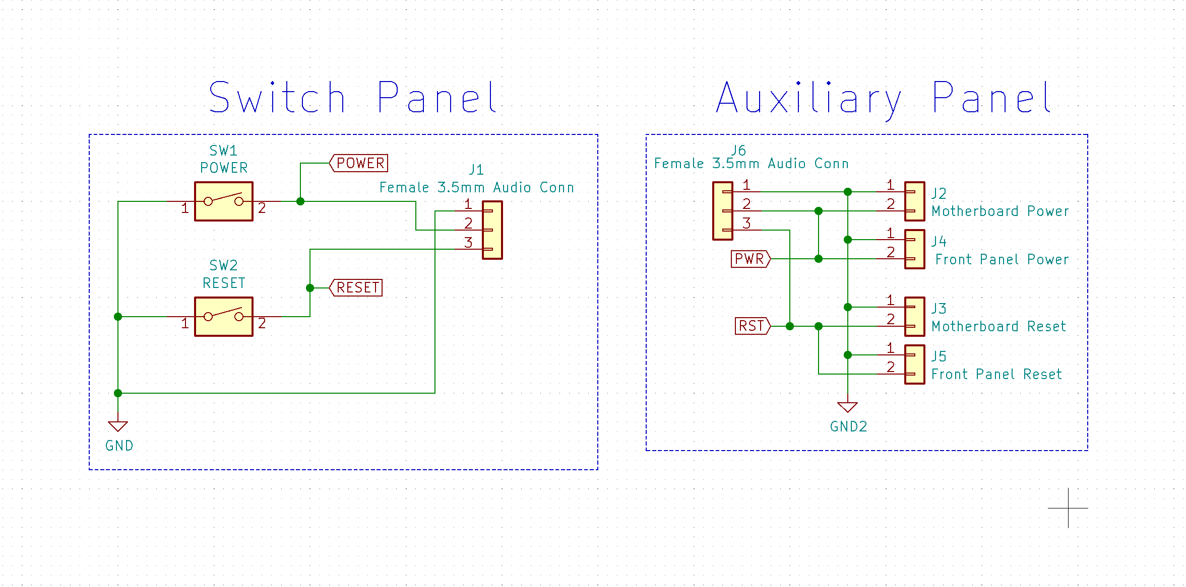
Connection to PCThe switch panel is connected to the PC motherboard with a 3.5 millimeter audio cable via an adapter board that has.1 inch pitch pins for connecting to the motherboard and to the existing front panel of a PC tower. The adapter board facilitates a connection that allows the existing power and reset buttons on the PC tower to remain functional while also adding the additional panel. See the above diagram of the connections between the switch panel, adapter board, PC front panel, and the PC motherboard.
The 3.5 mm audio connector is a common connector for accessibility devices such the Xbox Adaptive Controller. For the PCB side I used the SJ-3524-SMT SMD Headphone Phone Jack Stereo (3 Conductor, TRS).
Assembly and InstallThe PCB for the switch panel and the PCB for the adapter board were manufactured as one PCB which was cut into the two boards. The image below shows the manufactured PCB. They came out looking exactly as I imagined.
The components were soldered on the boards without issue and the sockets for the switches worked great. The assembled PCB for the panel is shown below.
The PCB is attached to a 3D printed plastic enclosure. The enclosure was printed in black PLA plastic with a Prusa i3 MK3 printer. I initially meant for the PCB to be attached to the enclosure via thread forming screws but I chose to just include clips into the 3D printed enclosure to avoid spending money on hardware.
In the first iteration of the enclosure the clips that held in the PCB board were far too stiff and the tolerances were too tight which made it difficult to assemble and even more difficult to disassemble. The PCB was scratched when removing this first iteration. In the next and final design I made the clips narrower to reduce the force required to assemble and the profile was reshaped to reduce stress in the clips. I also added more space between the board and the clips. This final design allows for easy assembly and disassembly and holds the board in securely. The image below shows the failed design next to the in-use design.
The adapter board was connected to the motherboard like shown in the diagram. This required the removal of the graphics card so that the motherboard's power and reset pins could be accessed. One end of an audio cable was connected to this adapter board and the other end was pushed through a hole in the back of my PC tower and connected to the button panel. I failed to take a photo of the adapter board connection before the graphics card was put back in.
I felt that the most flexible solution for mounting the panel was to simply use double sided tape on the back of the enclosure. The panel was mounted on one of the legs of my desk near my foot level.
Overall I was very happy with the design. It has proved to be incredibly useful. I now no longer need assistance to simply turn on my computer. It was fairly easy to install for anyone for who is somewhat familiar with building PCs.


Comments
Please log in or sign up to comment.