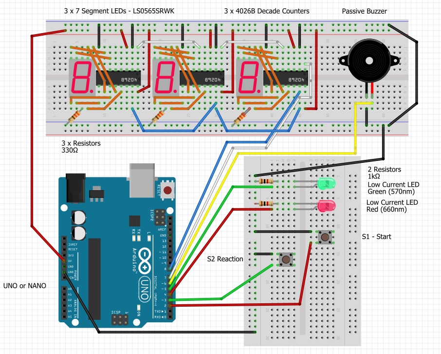
I decided to make a reaction timer as I wanted to learn about and experiment with the 7 segment LED display driven by a 4026B decade counter and built it round the Arduino UNO/Arduino NANO.
The timer operates as follows:
1. On connecting power, the red Get Ready light flashes twice to show that the system has booted up and the LED displays shows 000.
2. Press the Start button and the red Get Ready light turns on for a random time between 1 and 5 seconds.
3. The red light goes out, the green Go light turns on and the LED displays start to count in milliseconds.
4. Press the Reaction button as quickly as possible and the time stops counting and the green light goes out. If the user takes longer than 999 milliseconds then the buzzer is sounded and the display reset to 000.
5. The time of the last reaction, in milliseconds, will remain on the display until the Start button is pressed again.
7 Segment displayThe 7 segment display used has 2 rows of 5 pins located at the top and bottom. 7 pins are used for the 7 LED segments that form the number or letter to be displayed and the 8th pin controls the decimal point. The remaining 2 pins are common connections, in the middle of the top and bottom row. The display I used was a Multicomp Pro LS0565SRWK. The pin layout is as follows:
The LED segments must be protected with a series resistor to reduce the voltage. In theory, you should use a separate resistor for each segment to get a consistent brightness, however for simplicity I have used one resistor between the common pin and negative ground. This will mean that some numbers with fewer lit segments, e.g. 1, will be brighter than say the 8. If you are not happy with this then you can use 7 separate resistors, one on each of the segment pins.
I have used a 330 ohm resistor. Please adjust this as required to ensure that the voltage drop across the LED segments and the current are within the limits of the display you have used.
4026B Decade counterThe 4026B decade counter is an old style chip so it has limited power output but this is sufficient for our requirements. Most decade counters have coded output in binary, however the 4026B has seven output pins and powers them in a pattern that matches the pins of the 7 segment display. Hence, no driver is required to convert binary to the seven segment pattern.
The pin layout of the 4026B is as follows:
Pins are used as follows:
Pin 1 – Clock: Transitions when moved from Low to High and advances count by 1.
Pin 2 – Clock inhibit/disable: When High will stop counting. So connected to ground in our project.
Pin 3 – Display enable in: When High the current count is reflected in the display out pins a to g, so connected to the supply voltage in our project as we want the count displayed.
Pin 4 – Display enable out: Reflects the state of pin 3 to pass to other counters.
Pin 5 – Carry out: This pin shifts from Low to High when the counter reaches 9 and goes back to 0. This can act as a clock input for a second 4026B timer, for example to show the tens digit.
Pin 8 – 0v: The chip requires its own power connection and pin 8 is connected to ground (-ve terminal)
Pin 14 - Ungated “C” Segment: Can be used to restart the count after it has counted 0, 1 and 2. For use when displaying time in 12 hour format.
Pin 15 – Reset: Active on High. Resets the counter to 0 when this pin goes High.
Pin 16 - +V: Positive voltage supply. Normally from 3v to 15v but check the data sheet for the chip you have.
Other pins – Output pins: 7 output pins corresponding to the segments in the LED display.
The programThe program is commented so hopefully easy to follow. The only aspect to mention here is the clock output.
The tone() function generates a square wave, from LOW to HIGH and back, of the specified frequency. We are outputting a frequency of 1000hz which causes pin 7 to go high once a millisecond. This pin is connected to the clock input of the units counter resulting in the display counting in milliseconds.
No duration is set for the tone so it will continue until the user presses the reaction button and we call noTone() to stop the output.
Arduino pins usedI have not used pins D0 and D1 as these are also used for serial communication. Hence, if you wanted to change the program to use the serial monitor to display the value of “elapsed”, to check the timer was accurate, it would stop the timer working properly as it would change the INPUT_PULLUP setting for the pin.


_ztBMuBhMHo.jpg?auto=compress%2Cformat&w=48&h=48&fit=fill&bg=ffffff)


Comments
Please log in or sign up to comment.