This is a timer that can be used as a countdown timer for any purpose but was created to use when playing games.
This rechargeable version is an evolution of the my original project which can be found here. The changes are to to use an Arduino Pro Mini 3.3v rather than a Nano so it can run on a 3.7v battery and also to add 2 resistors for the battery monitor.
Once you set the turn duration, using the up and down buttons, simply press start when the turn starts and the timer will beep, the display will show "go" and the countdown will start. The countdown will display after 3 seconds. When the time is up, "End" will be displayed and a longer beep sounded. After 5 seconds the set duration will be redisplayed for the start of the next players turn.
You can terminate the countdown early by pressing the start button again.
The duration can be from a few seconds to 99 minutes and clearly it can be used as a timer for any purpose.
The up and down buttons can be held down to repeatedly change the time, above 60 seconds the increment is increased to 10 seconds.
The last set duration is stored in EPROM so is remembered when the unit is turned off.
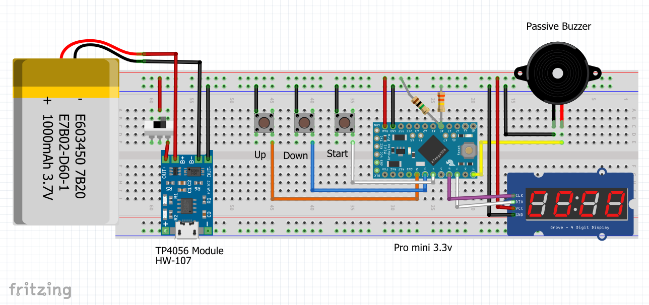
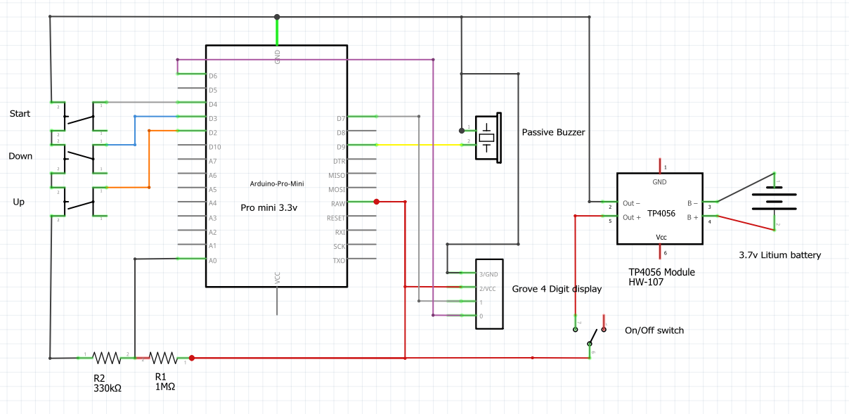
CircuitThe circuit is straightforward.
The 3 momentary switches connect pins D2, D3 and D4 to ground when pressed. The pins are set to INPUT_PULLUP, hence are normally HIGH and go LOW when a button is pushed.
The buzzer is connected to pin 9.
The 4 digit LED display has 4 connections.
- VCC to +5v
- GND to GND
- CLK to pin 6
- DIO to pin 7
2 Resistors, 1m ohm and 330k ohm are connected to pin A0 and are used to divide the voltage by approximately 4. This allows the battery voltage to be monitored by reference to a base voltage of 1.1v.
DisplayI am using a 4 digit 7 segment LCD display with a TM1637 driver. The one I used was a Youmile DR-YM-174, but any make should work.
The programThe program uses a library to drive the 4 digit display. I am using the library TM1637 v.1.2.0 by Avishay Orpaz.
The constants seg_go and seg_end define the segments that light to display the words "go" and "end". Five constants from seg_full to seg_low are used to display the battery level when the unit is first switched on. The state of the battery is displayed as 3 lines, 1 digit for low to 4 digits high. If the battery level is very low then the unit also beeps 3 times and displays "Lo".
The duration of the timer is held in a variable called "duration" and is set to 30 seconds by default. When Go is pressed the system checks to see if the current duration is the same as the last duration stored in EPROM. If not then the stored duration is updated. The library EEPROM.h is used to manage the EPROM memory.
ShowTime() takes a single parameter of the time in seconds to display. If more than a second has elapsed since the last call, the time is displayed using the call display.showNumberDecEx(number, 0b01000000, true, 4, 0). The second parameter turns on the dividing colon and the third displays leading zeros.
WaitForStart() contains a while loop that repeats until the start button is pressed. In the repeat the up and down buttons are checked and, if pressed, the duration changed. When the start button is pressed, "go" is displayed by the call to display.setSegments(seg_go) and the busser sounded.
TimeDuration() is then called which calls the time display in a loop until the time is up, or the start/stop button pressed, after which it displays "End" and sounds the buzzer.
After a 5 second pause, the process repeats.
Battery MonitorThe analog Input pin A0 is used to read the voltage. As the project runs from a 3.7v volt battery, the reference voltage used by the pin needs to be set to a regulated value as otherwise it would be comparing the battery voltage to itself. The statement analogReference(INTERNAL) sets the pin to compare the input voltage to a regulated 1.1v. It is therefore necessary to reduce the voltage on the input pin to less than 1.1v for this to work. This is done by dividing the voltage using 2 resistors, 1m and 330k ohms. This divides the voltage by approximately 4 so when the battery is fully charged, which is 4.2v, the voltage at the pin input is 4.2/4 = 1.05v.
// Read the monitor pin and calculate the voltage
float BatteryVoltage(){
 float reading = analogRead(MONITOR_PIN);
 // Calculate voltage - reference voltage is 1.1v
 return 1.1 * (reading/1023) * voltageDivider;
}
The function BatterVoltage(), reads the analog pin, which will range from 0 for 0 volts to 1, 023 for 1.1v and using this reading calculates the actual voltage coming form the battery.
A call is made to CheckBattery() on start up which in turn calls the BatteryVoltage() function to check the battery level.
The TP4056 charger used is provided with a regulating resistor of 1.1K ohm that provides a charge at a rate of 1, 000mAh. This is really too high for the 1, 000mAh battery used which should be charged at a maximum of 500mAh. It is fiddly, but you can remove the board mounted resistor (R3), or I find it easier to break it by scraping a knife across it as this leaves the post to solder to, and solder on an external resistor to reduce the current. Here is the table showing resistor values and current produced. (Check with a meter that you are still reading the correct resistance across the connection as it is easy to short these and this would cause damage.)


_3u05Tpwasz.png?auto=compress%2Cformat&w=40&h=40&fit=fillmax&bg=fff&dpr=2)
Comments
Please log in or sign up to comment.