Warning: This project will void your warranty. Proceed at your own risk.
Introduction
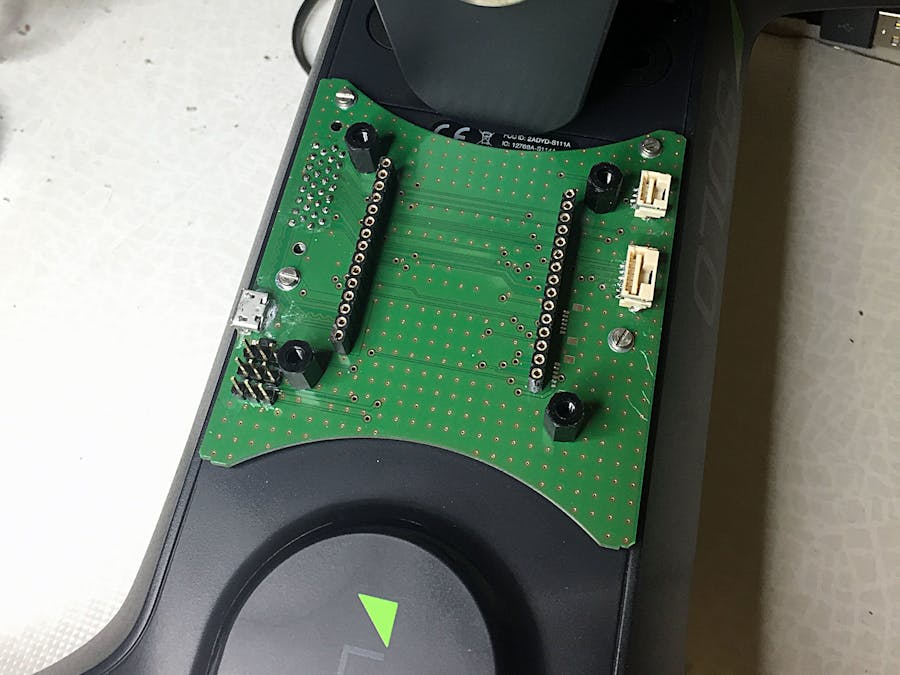
This hack extends the growing number of mods for 3DR Solo @ Hackster. We are using the 3DR breakout board as a basis. Since this is not yet commercially available, you may create your own one or seek out at the Solo Mod Group on Facebook to contact other builders to buy one.
Before you proceed, please ensure that you have removed the battery from Solo. The first step is to teardown your Solo. Please see here on how to do that.
Adding PWM Channels
In order to control additional servos, we first need to add the corresponding PWM channels to the extension port. Unfortunately 3DR decided not to make CH6-CH8 available. One reason could be that the controller does not have any spare controls which can be programmed. So CH6 is used also by the Gimbal Tilt paddle, and CH7 can be triggered by toggling the Pause button on the controller. So far, I could not detect a built-in controller command to trigger channel 8 (I'll buy a beer for the first one to find out :-))
First lets do the wiring. Therefore we connect pad 14 (PWM6), pad 18 and pad 19 (PWM8 and 7) on the main board to the corresponding pads on the extension board.
The following picture shows the meaning of the pads on the main board of Solo.
We carefully solder three cables to the pads 14, 18 and 19 on the main board and connect them with the corresponding pads 14, 18, 19 on the extension board carrying the extension plug and we are done with this part.
Adding the I2C Interface
While having Solo opened up, we can add also an I2C interface. With Solo, 3DR decided to obsolete I2C and move to UAVCAN instead. This is a move in the right direction, however there are only very few UAVCAN compatible devices available yet. In order to allow the connection of I2C sensors and equipment, we want to add an I2C interface to the extension port, too. Therefore we solder a 2 pin cable to pad 20 and 21 of the extension board as shown in the picture above. The cable should be about 15cm in length since we need to tap into one of the existing I2C busses inside Solo. Pad 20 and 21 are reserved for IO-SWDIO and IO-SWDCLK but not used by Solo's extension port - therefore are available for our mod.
Solo has 2 I2C busses, I2C-1 used for the compass, and I2C-2 used for the battery monitor. The following picture illustrates how to tap into the compass cable. The green cable is SCL, and the white cable carries the SDA line of the I2C bus.
The following picture shows the connectors of the I2C battery bus. The Pixhawk 1 compatible I2C sensors should be connected to the I2C bus used by the compass. To connect any sensors to I2C-2 would require a custom version of the Solo FW.
Disclaimer: you have to test your sensor if it works with Solo. Be aware of that any issues in the I2C communication can result in a brownout of the Pixhawk processor and a subsequent crash.
Having done all this, we can assemble Solo carefully and start playing with the new capabilities.
Enabling PWM Channels in Mission Planner
In order to trigger a servo or other devices through PWM, we need to activate the channels in Mission Planner. Therefore connect to Solo WiFi, and open the full parameter list. Then set the variables RC6_FUNCTION, and RC7_FUNCTION to 1. Save the settings to Solo.
Then connect a servo to PWM6 and PWM7 to the breakout board as shown in the following picture.
Now by using the paddle on the controller you can trigger the servo in parallel to the gimbal tilt movement. By pressing the Pause button you can trigger a servo on PWM7 as shown in the video below.
Have fun with Solo and please report your applications built on top of the breakout board!


Comments
Please log in or sign up to comment.