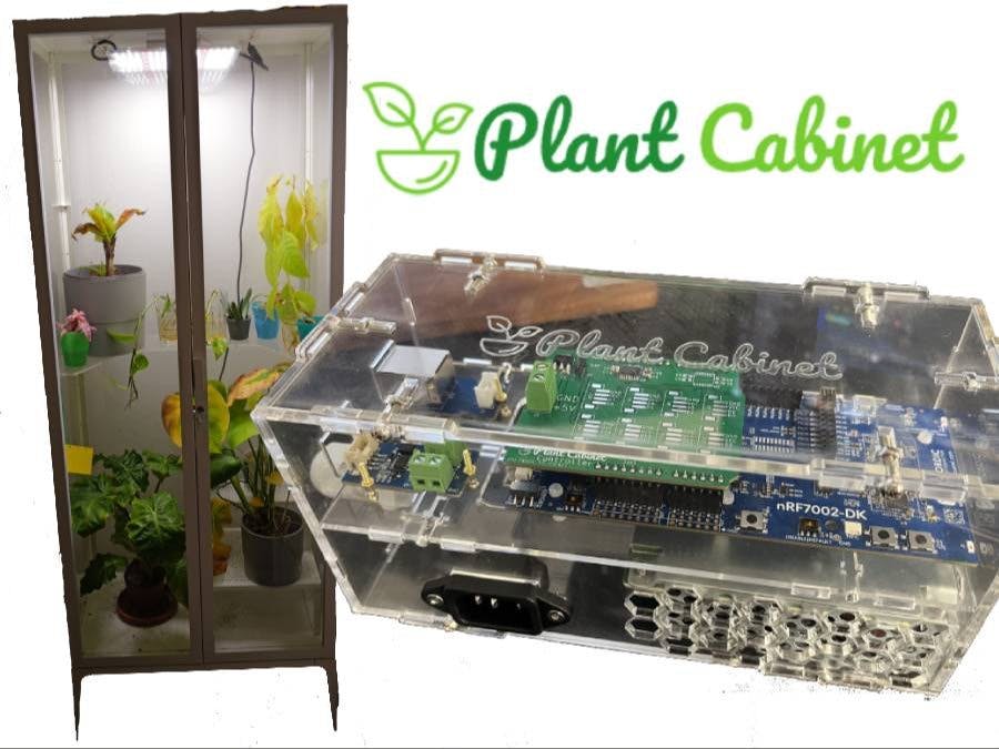
The PlantCabinet🪴 Controller is your personal assistant for the optimal growth of your tropical plants in the indoor plant cabinet! This innovative device allows you to precisely monitor and control the conditions for your green protégés to create an ideal growing environment.
The controller is equipped with a variety of features aimed at meeting the needs of tropical plants. From adjusting the special plant LED light to regulating airflow with an integrated fan, this controller offers a comprehensive solution for indoor gardeners who want to create the optimal breeding ground for their exotic plants.
The device integrates seamlessly into your smart home. Thanks to the advanced smart home protocol Matter, you can now effortlessly integrate your plant garden into your smart home and take control of the conditions with just a tap or combine it with other devices.
In this guide you will learn step by step how to assemble and configure your own PlantCabinet🪴 Controller. Discover why an indoor plant garden house is invaluable, especially for propagating plants and helping tropical crops thrive. Let's pave the way to a thriving, tropical paradise within your own four walls!
We got different requirements for the hardware:
Brain & Communication:
- Get the data from the sensors, publish them, receive commands and control the actors
The nRF7002-DK is the brain of the project. The host processor, the nRF5430, has more than enough power, ram and flash for this project. And it also can communicate via BLE (Bluetooth low energy), Thread and the development kit also has a NFC antenna. The Wi-Fi Companion IC, the nRF7002, can communicate via 2.4 GHz or 2.4/5 GHz. So this development kit is the perfect starting point for Matter applications, since you can use BLE or NFC for commissioning the device and Thread or Wi-Fi for communication!
The on-board SEGGER J-Link debugger/programmer make your live also easier, since you can debug your application and not just rely on log messages!
Actors:
- Turn the plant LEDs on and off:
The plant LEDs need 230v to we can't just turn them on/off with the microcontroller. We need a relay which can handle the voltage and power needed.
⚠️ We use main's voltage! Please make sure to ask a professional electrician for help!
- Provide an airflow:
We use a 12v fan which can be controlled via PWM (pulse width modulation). Since the microcontroller can't handle 12v we could use a relay. But since we need a faster reacting device a relay it too slow. So we you a mosfet which can turn on/off really quick but also can handle the 12v.
Sensors:
- Measure environment (Temperature and humidity) of the cabinet
There are different sensor capable for this job. I chose the BME680 since it also measure the air pressure and air quality besides the temperature and humidty.
- Measure the soil moisture
There are different sensors which could measure the soil moisture. In my experience sensors which use capacitance are far better, because they don't rot away by time.
In the Matter Application Cluster specification in the chapter "Water Content Measurement" describes the a cluster, which can be used to measure the soil moisture. But since it isn't implemented in the current Matter Version 1.2, we skip this sensor.
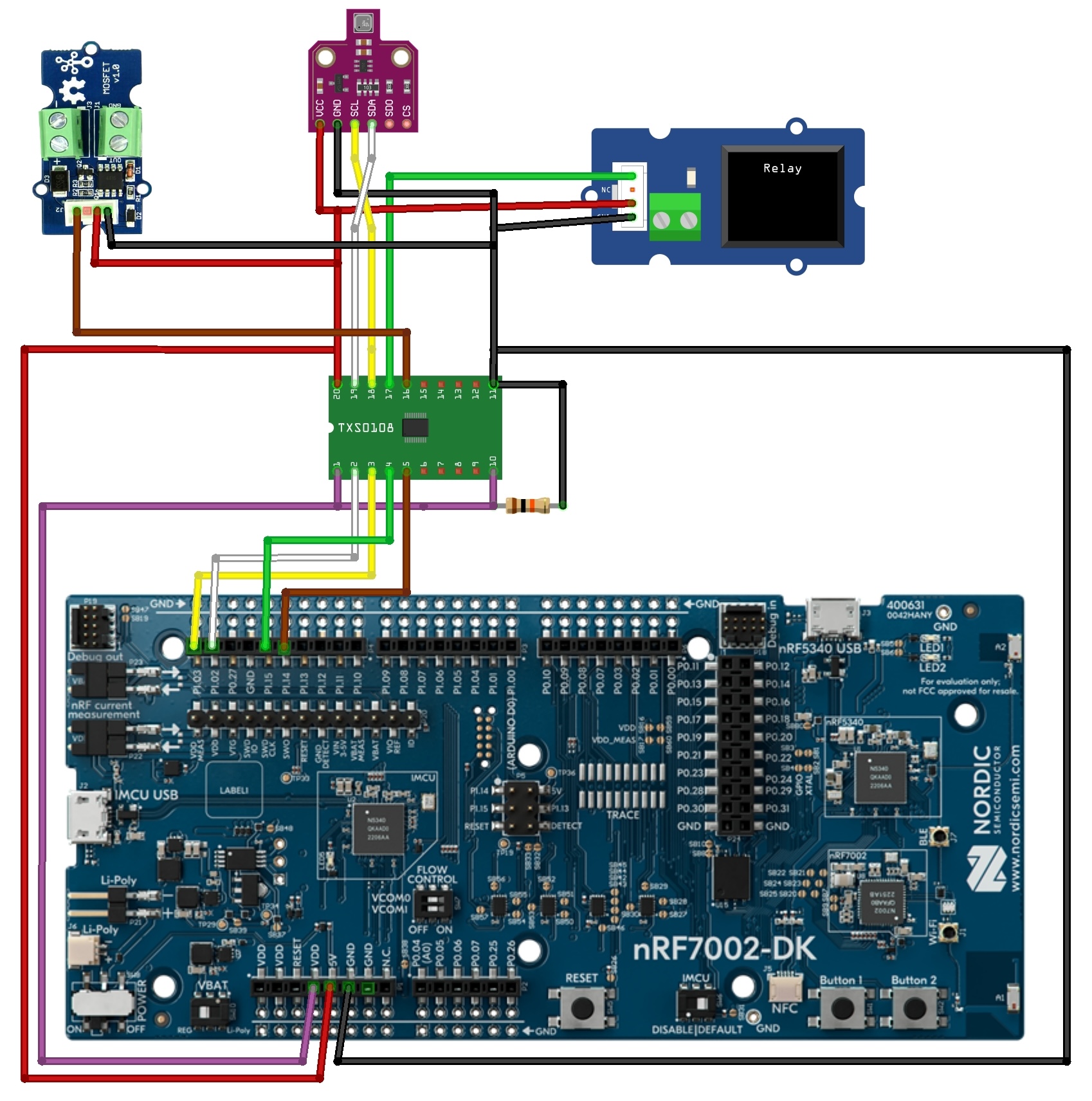
So the hardware looks like this:
Since the nRF7002-DK only provides 1.8v (See the note down the page) but we need 3.3v or 5v for the sensors, one essential part of the hardware is the TXS0108E. It is logic level converter which provides eight full duplex channels and transforms the signal from 1.2v-3.6v to 1.65v-5.5v and vice versa. So we can communicate for example with the BME680 sensor via I2C and read and write data with the correct voltage. We need a pull-up resistor of 10k ohms to enable the chip. On the breakout boards for the TXS0108E there are decoupling capacitors installed, not like in the schematic above.
The BME680 is connected via the TXS0108E to the nRF7002-DK using I2C's SDA (P1.02) and SCL (P1.03) pins. For the relay and mosfet we just need one signal pin for each to turn on/off (P1.15 and P1.14). There pins are also first connected to the TXS0108E to get a signal with 5v.
The nRF7002-DK can be used with the RTOS Zephyr. Nordic provides it own fork of Zepyhr called nRF Connect SDK. The best to get familiar with the nRF Connect SDK, how to install it and the basic usage is to use the free DevAcademy from Nordic (Btw. you can get a certificate, which always looks good on your resume!). Best start with the nRF Connect Fundamentals Course.
To get familiar with Matter a good starting point is the webinar of Nordic Semiconductor
and also there is whole section in Nordic's documentation to get started.
For this project no custom driver must be implemented, because the BME680 is already implemented.
For the relay we just need to control a GPIO pin. For this the custom binding "power_switch" was used from an example. Here you can define the GPIO pin on which the relay is conected.
The fan is controlled via PWM. A custom binding "pwm-fan" was created. You can define the pwm pin and the off, low, med & high pulse if you use an other fan.
Just edit the "overlay"-file or create a new one, if you use other pins or an other board.
To flash the app to the board:
- Install VS code and install the nRF Connect for VS Code Extension Pack
- Use the nRF Connect for Desktop app to download the Toolchain Manager
- Open it and install the nRF Connect SDK 2.4.2
- Click on "Open VS Code"
- Click on the nRF Connect extension
- Open an existing project
- Create an new build configuration
- Connect the nRF7002 DK, when not done before, and flash it!
Matter is a standardized and open-source smart home protocol that facilitates seamless communication and connectivity between various smart devices, ensuring interoperability and ease of integration within a smart home ecosystem.
So it's perfect for this application, because we can pair the PlantCabinet🪴 Controller with other devices, like a humidifier which is connected to a Matter enabled smart socket.
Matter uses a specific architecture, see the documentation from Nordic for more details: Matter architecture
The PlantCabinet🪴 Controller is one node, which has different endpoints. The following endpoints are created with the zap-tool:
- Endpoint 0: Matter Root Node (Which a default endpoint for informations about the system)
- Endpoint 1: Matter Temperature Sensor
- Endpoint 2: Matter Pressure Sensor
- Endpoint 3: Matter Humidity Sensor
- Endpoint 4: Matter On/Off Light
- Endpoint 5: Matter Fan - It uses the Off/Low/Med/High FanModeSequence
The zap tools generates code for us and makes the management of the endpoints and there attributes easier. When you want to edit the config or generate the code by yourself you need to adjust the path to the zap file (Line 21 and 29):
"package": [
  {
    "pathRelativity": "relativeToZap",
    "path": "../../../../../opt/nordic/ncs/v2.4.2/modules/lib/matter/src/app/zap-templates/zcl/zcl.json",
    "type": "zcl-properties",
    "category": "matter",
    "version": 1,
    "description": "Matter SDK ZCL data"
  },
  {
    "pathRelativity": "relativeToZap",
    "path": "../../../../../opt/nordic/ncs/v2.4.2/modules/lib/matter/src/app/zap-templates/app-templates.json",
    "type": "gen-templates-json",
    "version": "chip-v1"
  }
],
If you want to create a new endpoint the "Adding clusters to Matter application"-guide from Nordic is a good starting point!
Since we use main power we don't need to save energy, so wifi was use instead of Thread for the communication.
The endpoints for temperature, pressure and humidity getting updated by a timer. Every 5 seconds the method AppTask::SensorTimerTimeoutCallback is called. This method puts an AppEvent with the handler AppTask::SensorMeasureHandler in the queue:
void AppTask::SensorMeasureHandler(const AppEvent &)
{
  const int result = sensor_sample_fetch(sBme680SensorDev);
  if (result != 0) {
    LOG_ERR("Fetching data from BME688 sensor failed with: %d", result);
    return;
  }
  UpdateTemperatureClusterState();
  UpdatePressureClusterState();
  UpdateHumidityClusterState();
}
This fetches the sensor data and updates the clusters for each endpoint with the transformed data.
The command to turn the light on or off or change the speed of the fan is handled in the zcl_callbacks.cpp file. The method MatterPostAttributeChangeCallback checks which cluster, endpoint and attribute was given and add the AppEventType::RelayOn, AppEventType::RelayOff or AppEventType::ControlFan with the according handlers to the queue:
void MatterPostAttributeChangeCallback(const chip::app::ConcreteAttributePath &attributePath, uint8_t type,
uint16_t size, uint8_t *value)
{
  if (attributePath.mClusterId == OnOff::Id && attributePath.mAttributeId == OnOff::Attributes::OnOff::Id && attributePath.mEndpointId == 4) {
    AppEvent event;
    if (*value) {
      event.Type = AppEventType::RelayOn;
      event.Handler = AppTask::RelayOnHandler;
    } else {
      event.Type = AppEventType::RelayOff;
      event.Handler = AppTask::RelayOffHandler;
    }
    AppTask::Instance().PostEvent(event);
    return;
  }
  if (attributePath.mClusterId == FanControl::Id && attributePath.mAttributeId == FanControl::Attributes::FanMode::Id && attributePath.mEndpointId == 5) {
    if (*value < 0 || *value > 4) {
     return;
    }
    AppEvent event;
    event.Type = AppEventType::ControlFan;
    event.Handler = AppTask::FanModeHandler;
     event.ControlFanModeEvent.ControlFanMode = static_cast<::ControlFanMode>(*value);
    AppTask::Instance().PostEvent(event);
    return;
  }
}
If you want to commission the device you can scan the following qr code:
or use the manual pairing code: 34970112332
Custom PCBIn order to simplify the organization in the enclosure a bit, a separate circuit board was developed. It contains the logic converter and connections for the Grove connections, also it's own LDO voltage regulator for 3.3v, so you could choose between the delivered 5v or 3.3v.
Unfortunately, my soldering skills weren't good enough, so the small pins on the Logic Converter kept causing short circuits, as you can see in the picture 🙈. So I used the breakout board version.
To fit all the hardware and to protect the users from the 230v a enclosure is necessary. It was made from plexiglass using a CO2 laser. A model was created and exported using Fusion360.
The idea of the case is that it can be connected with just a few screws, so that it can also be quickly repaired or expanded.
In the co:hub66's fablab, a CO2 laser is available for a small contribution. It was used to cut out the case and engrave the logo.
CHIP toolYou can read the values and send commands via the CHIP tool. It is a terminal program for testing your Matter application. See the "Working with CHIP tool"-guide how to build it. Then you can use the following commands:
- Pair with device id 1:
./chip-tool pairing code-wifi 1 <YOUR_WIFI_SSID> <YOUR_WIFI_PASSWORD> MT:6FCJ142C00KA0648G00- Read temperature:
./chip-tool temperaturemeasurement read measured-value 1 1- Read pressure:
./chip-tool pressuremeasurement read measured-value 1 2- Read humidity:
./chip-tool relativehumiditymeasurement read measured-value 1 3- Read relay state:
./chip-tool onoff read on-off 1 4- Turn relay on:
./chip-tool onoff on 1 4- Turn relay off:
./chip-tool onoff off 1 4- Toggle relay:
./chip-tool onoff toggle 1 4- Read fan mode:
./chip-tool fancontrol read fan-mode 1 5- Write fan mode:
./chip-tool fancontrol write fan-mode 1 1 5Unfortunately, the Apple Home app does not reliably recognise all sensors, so I started developing an app in the cross-platform framework Flutter. I've started to write a own Flutter Matter plugin at work, so you could use Matter devices with iOS and Android in a Flutter application. But it needs some rework, then it will be published soon.
After the code of the app has been further cleaned up, it can be published.
Here's a little preview:


_t9PF3orMPd.png?auto=compress%2Cformat&w=40&h=40&fit=fillmax&bg=fff&dpr=2)


Comments
Please log in or sign up to comment.