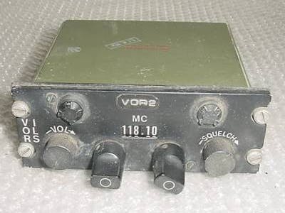
The first rule is to do No Harm to the avionics, in this case, the radio head. The head is C-3436A/ARN-30. On the Internet, I found TM 11-1520-211-35 which is the devices manual. So it's has 3 ARC connectors on the back and we could not get the pin-out. Luckily I had built an interface cable a few years ago. The Cable has three(3) ARC connectors on one end and two (2) male DB-25 females on the other. So grab the DVM and start pinning it out.
So you have your pin out so now what?
Please Note: The ARC family of connectors where used from before WWII to the start of Vietnam, they are very hard to find.
THE ANALYSIS: OK, this radio is like most others but simpler, and not ARINC-410. So I have to define what goes in (commands) and what comes out (information). The information side will be called Transmit and the command side Receive.
Transmit Side
- Power Switch: Two States: On - Off
- Frequency: 108 to 126 in unit steps, plus a Blank
- Frequency Fractions: .00 to .90 in unit steps.
- Volume Control: Analog output
- Squelch Control: Analog output
Receive Side
- Panel Lights: Two States: On - Off
- Dial Lights: Two States: On - Off
Since the lamps are 24 volts, we will need a relay to drive them. Now I am old school so I normally wire-wrap my one-offs. Please note the Molex connector, part number 15-24-4441 is a standard power connector, normally found on your hard-drive. I also used Nylon 4-40 hardware (no shorts).
Lastly, I wrote a small python script to receive the output and put it on my screen.
If you wish to read more about my simulator please read my blog at Element14.
If you wish to read more about DIY Cockpits please see cockpitfestusa.


_wzec989qrF.jpg?auto=compress%2Cformat&w=48&h=48&fit=fill&bg=ffffff)


_3u05Tpwasz.png?auto=compress%2Cformat&w=40&h=40&fit=fillmax&bg=fff&dpr=2)
Comments
Please log in or sign up to comment.