A solar boiler is great because it gives you hot water using free-sun-energy, but what if there is not enough sun or someone already used all the hot water ? This project helps you take the right decision. It warns you when you run out of hot water and allows you to turn on the electric heating. It also let you know when you can take a bath or shower !
Goals :
Alert me when the Hot Water goes below a certain threshold
Manual Control heating (On/Off)
Show current temp values,
Heating status (on/off)
Show historical Sensor/Actuator values (graphs)
- Show power consumption (historical graph)
Typically Hot Water Boilers are in a location within households where Internet connection is available. Therefore i opt for this project to use wireless technology based on Xbee to transfer sensors and actuator data from a receiver which is placed at the boiler side to a Wireless device (Controller) which is connected to the internet and acts as a ‘gateway’ to the SmartLiving IoT Cloud platform.
The Receiver Module :
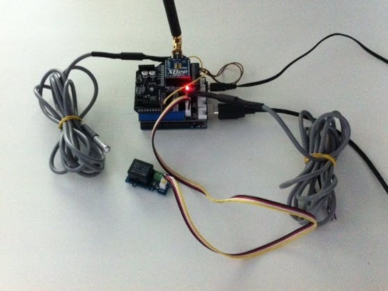
For the receiver module, i used a Standard Arduino board in combination with the Grove shield for arduino and an Xbee Shield.
For measuring the temperature i have added 2 Onewire Temperature sensors (DS18B20). These sensors are Digital Temperature sensors where multiple One-Wires sensors can be hooked up to 1 digital port on the Arduino. I use these type of sensors in this project because they give a good resolution for the temperature range we want to cover.
Features
- Requires only one wire for data interface
- Waterproof
- Grove compatible
- Accepts 3.0V to 5.5V power supply
- Wide temperature range: -55°C to +125°C
- High accuracy: ±0.5°C( -10°C to +85°C)
Further, i have added a Grove relay to control the electric heating resistor in the Solar boiler, which i can control remotely in case a need more hot water.
In the picture below, you find the complete setup of the receiver module.
The Controller module
For the Controller module, we made use of an Iboard of ITEAD. This is an alternative Arduino board with onboard Ethernet and XBee sockets, which is ideal for this project.
The main purpose of the ‘controller’ module is to bridge information from the SmartLiving IoT platform to Xbee and reverse.
Communication Flow
The next picture gives a high level view of the communication flow between the different components
Configuring the XBEE modules
I have used 2 XBEE XB24-ZB series 2modules. These are fantastic modules which allow you to setup a Meshed network communication just by configuring the modules. The Series 2 modules can work in API mode, which is useful to communicate with them with an arduino.
For the controller modules, you have to configure the XBEE as a coordinator. I have used the following firmware & version:
-
Modem XBEE : XB24-ZB
-
Function Set : ZIGBEE ROUTER API
-
Version : 23A7
For the receiver module, you have to configure the XBEE as a router. I have used the following firmware & version :
- Modem XBEE : XB24-ZB
- Function Set : ZIGBEE ROUTER API
- Version : 23A7
The PDF below includes all detailed XBEE config.
Using the SmartLiving IoT platform
For this project i used the SmartLiving IoT Platform to setup e-mail alerting and allow me to sense and control the hot water boiler via my mobile phone.
There is a nice tutorial available on how to use an Arduino with the SmartLiving platform : http://docs.smartliving.io/Get_Started/Arduino
One's you have created your SmartLiving account and created your device, you can use the Arduino code below for the receiver module and the controller module.
Before uploading the sketch of the gateway, modify your device-id, client-id and client-key.
When the sketch is uploaded and executed, the assets are created in the SmartLiving IoT platform under your device.
We now can create a number of rules to alert us in case of the water getting under a certain threshold or above a certain level. and we can also control assets from our smartphone, using the Android makers App from SmartLiving.


_ztBMuBhMHo.jpg?auto=compress%2Cformat&w=48&h=48&fit=fill&bg=ffffff)


Comments
Please log in or sign up to comment.