Since Publication of the Ardutester V1.13 ( with limited number of Display Interfaces, mainly the popular 4 Bit Parallel 1602 LCD featuring 2 lines by 16 characters, HD44780 controller, was supported. ). Over time, I was adding other displays and modernizing the Software drivers by using the Arduino wire Library for the High Speed native I2C, which brings the performance needed for a responsive graphical OLED Display.
Because the Ressources needed for the graphic version of the ArduTester, a MEGA is needed when a Graphic Display is choosen. The more timers in the MEGA allow also to have the Freq. Counter feature available.
The basic UNO can now run the 1602 16 X 2 LCD with I2C interface, in order to reduce the wiring to the minimum.
This project focuses on the configuration of the latest Software Version for 4 popular hardware configurations below ( of course, more display variants like 1306 with SPI or only Arduino Serial Monitor, with no Display at all, are possible... ).
If you are new to ArduTester, explore first the
ArduTester V1.13: The Arduino UNO Transistor Testerfor more detailled information about the ArduTester.
The 4 Configurations detailled in this Millenium project are :
- The UNO with 1602 LCD Parallel Interface
- The UNO with 1602 LCD with I2C Interface
- The MEGA with 1602 LCD with I2C interface ( and Freq. Counter )
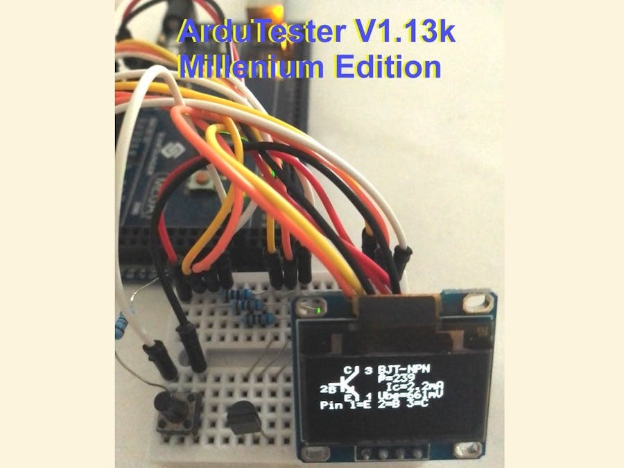
- The MEGA with Graphic Display 1306 OLED 128 X 64 with I2C interface ( and Freq. Counter ).
The ArduTester is complying to "the sustainable electronics", because if by mistake you kill the Atmel Chip, you can always repair the ArduTester by replacing the Arduino Board or repairing it ( The Atmel is on a socket in the UNO ) , so you have not to discard all the Tester, minimizing the electronic waste production.
Configuration 1, the classic : UNO with 1602 Parallel interface
Select Arduino / Genuino Uno Board in the IDE
The Makefile.h entries should look like this, all further Displays entries are commented out.
Express wiring instruction : TP1..3 - A0..A2, RL..RH - D8..D13, Test - A3
DB7..DB4 - D2..D5, E -D6, RS - D7, R/W to GND, K to GND, A to 3.3V, VO to Contrast Potentiometer, VSS to GND, VDD to 5V
Configuration 2, lesswiring : UNO with 1602 withI2C interface
Select Arduino / Genuino Uno Board in the IDE
The Makefile.h entries should look like this. ( uncomment Lines 27-28 ).
Express wiring instruction : TP1..3 - A0..A2, RL..RH - D8..D13, Test - A3
GND to GND, VCC to 5V, SDA to A4, SCL to A5
Configuration 3, MEGAwithFreq.Meter : MEGA with 1602 withI2C interface
Select Arduino / Genuino Mega or Mega 2560 Board in the IDE
The Makefile.h entries should look like this. ( leave Lines 27-28 uncommented ).
Express wiring instruction : TP1..3 - A0..A2, RL..RH - A8..A13, Test - D29
GND to GND, VCC to 5V, SDA to SDA 20, SCL to SCL 21
Configuration 4, MEGAwithOLED&Freq.Meter : MEGA with 1306OLED128X64 withI2C interface
Select Arduino / Genuino Mega or Mega 2560 Board in the IDE
The Makefile.h entries should look like this. ( cooment out lines 27-28 ).
Express wiring instruction : same as Configuration 3
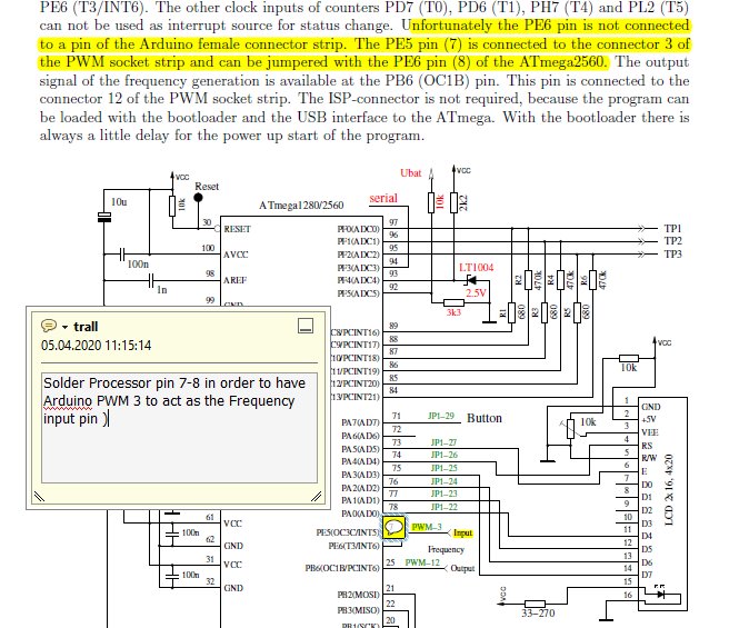
Note for the Frequency Meter, there are 2 pins to shorcut ( needs a solder Iron ) on the Processor pins of the MEGA.
After this difficulty, you can enjoy the Frequency meter !
Arrow 1 is the soldering of pin 7-8 of the processor
Arrow 2 The Orange wire connected to PWM 3 is picking up the 50Hz noise...


_ztBMuBhMHo.jpg?auto=compress%2Cformat&w=48&h=48&fit=fill&bg=ffffff)
_wzec989qrF.jpg?auto=compress%2Cformat&w=48&h=48&fit=fill&bg=ffffff)


Comments
Please log in or sign up to comment.