


Hardware components | ||||||
 |
| × | 1 | |||
| × | 1 | ||||
| × | 1 | ||||
| × | 1 | ||||
Software apps and online services | ||||||
 |
| |||||
This project represents an system for monitoring possible water leaks caused by failure of hot and cold water pipes or hoses in the house (kitchen, bathroom,...).
I started this project because I didn't find any system that fits on my needs regarding to this possible issue.
It can operate in 4 ways:
- stand alone;
- connected to a RS485 Master (device with UI used to read data and send commands to this module); in this case, this module will act as a slave;
- connected to Smart house using an Zigbee custom module (using RS232 communication);
- connected in the same time to RS485 Master and Smart House through Zigbee network.
This device will monitor an water drop sensor and will close the hot water and cold water valves when water leak is detected; moreover, a light and a sound alarm will be triggered if any water leak is detected too.
OBS: for this project, the board will operate in standalone mode; RS485 Master (UI) and Zigbee module are the subject of improvement of this project; changes will only be possible for serial communication between this module and the one with UI or Zigbee; these changes will not affect the basic functionality of this device.
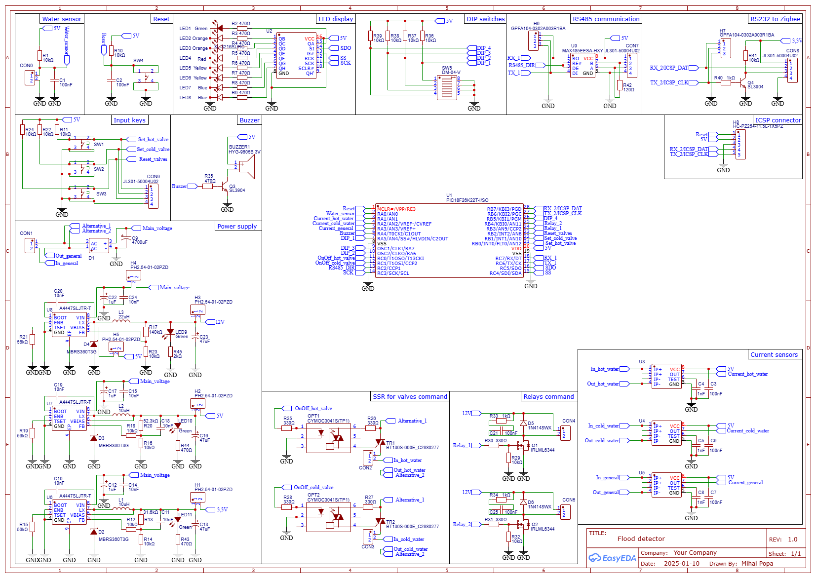
1. PresentationThis project is created around the Microchip MCU PIC18F26K22. I chose this particular MCU because he has 2 USARTs, comparator, ADC and enough PINs for all the connections.
The board module contain several components, such: buttons, connectors for external communications, connectors for valves, water sensor and power supply.
Buttons are used to turn On and Off the valves:
- SW1 - turn OnOff hot water valve;
- SW2 - turn OnOff cold water valve;
- SW3 - Reset water valves and alarm condition.
All three buttons are connected to INT0, INT1 and INT2 hardware interrupt pins.
The sensor for water flood is connected to comparator 1, negative input, RA0 pin.
The device status is displayed on 8 LEDs connected to an 74HC595 shift register.
The LEDs signification is:
- Valves ON - used to signal that one or both valves are On;
- Hot water valve FAIL - used to signal that Hot water is started but no current "flow" from it; that mean the valve is in "open" status or damaged;
- Cold water valve FAIL - used to signal that Cold water is started but no current "flow" from it; that mean the valve is in "open" status or damaged;
- Alarm/Valves Off - used to signal a water leaks is detected and all valves are switched Off;
- RS485 activated - used to signal that the communication with UI over RS485 is activated;
- Zigbee activated - used to signal that the communication with Zigbee module (used for Smart house integration) is activated;
- Relay_1 ON - used to signal that relay 1 is activated (optional);
- Relay_2 ON - used to signal that relay 2 is activated (optional).
DIP switch: on board is an DIP switch from where we can activate/deactivate some function; here is the switch explanation:
- Activate RS_485 - activate/deactivate communication with UI/PC using RS485 protocol;
- Activate_Zigbee - activate/deactivate communication with Zigbee module fo link this board with Smart House (not ready yet!);
- Buzzer-On - activate/deactivate buzzer, used to start-up sound or alarm sound;
- Other - not defined yet (maybe, from here I can set the board ID, in case that will be used two bords to communicate with one UI).
Connections on board:
A. Valves are connected as follow:
- hot water valve is connected to CON2 on PCB Hot Water Valve;
- cold water valve is connected to CON3 on PCB Cold Water Valve;
B. Power supply is connected to CON1 on PCB;
C. Communication with RS48with and Zigbee module is done as follow:
- with RS485 UI module through CON7 on PCB;
- with Zigbee module through CON8 on PCB;
D. Sensor for water flood is connected to CON6 on PCB Water sensor;
E. External buttons, used to start/stop/reset water valves and can be mounted on the sensor case use CON9 on PCB;
F. Relays are connected as follow:
- Relay 1 on CON4 on PCB;
- Relay 2 on CON5 on PCB.
OBS: In addition to monitoring the water sensor, this device can separately activate two relays, which do not interfere with the monitoring system but which I need in the upgrade process of the existing system; more precisely: I need to switch the use of the 220V main between two consumers; the switching is done according to the rule: if relay 1 - ON then relay 2 - Off and vice versa; never both relays ON.
Ports and connections explained:
Valves used in this project are powered using alternative current.
OBS: carefully calculate the current consumed by the water solenoid valves so that it does not exceed the maximum power delivered by the transformer; in addition, a margin of 500mA must be added for the MCU and the rest of the components.
For this project I will use a normal transformer that will be compatible with valves coils (I use coils that will work with 24Vca) and can deliver ~19 V ca and ~3A.
The board contain all the necessary components to rectify and stabilize the supply voltage. After rectification and filtering, the resulting DC voltage will enter 3 separate power supplies, created around the A4447 IC from Allegro.
Important: the maximum voltage input ca is 32V ca, from the transformer!
These three power supplies will generate the following voltages:
- 3.3V - used for Zigbee Module;
- 5V - used to power the microcontroller, current sensors and most of the components;
12V - used exclusively to power the 2 additional relays.
To calculate the all three voltages, I used the following formula, from A4447 IC datasheet: Vout = Vfb * (R2/(R1+R2)) (page 5, from datasheet). for A4447, Vfb value is 0.8V.
The values for each power supply are:
a. for 3.3V: R1 = 31.6Kohm, R2 = 10Kohm;
b. for 5V: R1 = 52.3Kohm, R2 = 10Kohm;
c. for 12V: R1 = 140Kohm, R2 = 10Kohm.
OBS: the components R1 and R2 are referring to only one power supply (generic one); because in this project I used 3 power supplies, the components notation are updated in the schematic conforming the above formula.
To calculate the inductance value, for each power supply, I used the general formula for buck converters: L = ((Vin-Vout)*Vout)/(fsw * deltaIl * Vin), where elements are:
- Vin - maximum voltage input;
- Vout - output voltage;
- fsw - switching frequencies in Hz;
- delta Il - ripple current (variation of current through inductor).
So, for all sources, using the following data, the inductance value is:
a. for 3.3V: Vin = 24V, Vout = 3.3V, fsw = 1MHz (specified in datasheet), delta Il = 0.3*Ioutmax = 0.3*1A = 0.3A (assuming a ripple of 30%), Ioutmax = 1A => L = ~10microH;
b. for 5V: Vin = 24V, Vout = 5V, fsw = 1MHz (specified in datasheet), delta Il = 0.3*Ioutmax = 0.3*1A = 0.3A (assuming a ripple of 30%), Ioutmax = 1A => L = ~10microH;
c. for 12V: Vin = 24V, Vout = 12V, fsw = 1MHz (specified in datasheet), delta Il = 0.3*Ioutmax = 0.3*1A = 0.3A (assuming a ripple of 30%), Ioutmax = 1A => L = ~22microH.
OBS: I have chosen this A4447 IC as a power supply because it accepts a wide range of input supply voltages, between 8 and 50V, according to the datasheet (attached).
Each power supply output can be disconnected from circuit using a specific jumper (see schematic); exception is for 12V power supply: it use a jumper also for power input.
3. How it is workingThe device will start/stop the water valves (using 3 puss-buttons, from PCB and/or remote sites, from UI, over RS485 or Zigbee), will monitor the valve status (using 2 current sensors) and will trigger an alarm and turn off the valves if water leaks is detected (from water sensor).
After reset or power on, all valves are off and alarm is cleared. Then, the DIP switches status is checked to activate/deactivate several functions, depend on the position; after that, the application will start to monitor the water sensor.
All the status of valves and alarms will be sent at request to UI and/or Smart home.
The water flood sensor used is a very common one, called "Rain drop sensor":
This sensor is connected to a comparator input from MCU, at pin RA0.
When the sensor is dry, the resistance is ~infinite and the input of comparator 1 stay at 5V (see circuit schematic).
When the sensor become wet, then the resistance drop dramatically and the input voltage at pin RA0 become ~1, 3V. In this moment, the comparator generate an interrupt and the following actions are performed:
- all valves are off, to prevent the water flood;
- led alarm is turned on (on the board);
- sound alarm is triggered (if is activated).
The alarm condition can be reset using the following actions:
- reset valves;
- reset board using the reset MCU button.
To be sure that valves are working, 2 current sensors are connected in series with each valve; these sensors will monitor the valve current consumption and will trigger an alarm if the valve ON command is sent but the current consumption is low. Another current sensor is connected in series with the secondary of the power transformer, to monitor the total power consumption; this will be used to calculate the energy consumed by the system. The total energy consumed will be calculated on the UI and/or Smart Home, based on the current value sent by the board and the voltage on the transformer secondary (measured with a voltmeter).
OBS: for this project, I used the existing water valves. These valves was purchased from local market, from the Romanian company Calor:
To communicate with the UI interface and/or the Zigbee module, we used both USART modules in the PIC18F26K22, as follows:
- USART1 is used to communicate with the UI/PC via the RS485 protocol;
- USART2 is used to communicate with the Zigbee module.
Both USARTs use the same set of commands, shown below:
Important: the module will not send anything on the serial (EUSART 1 or 2) without an external request (UI/PC or Zigbee)
The stop, start and reset valve command will have to be followed by the status command, because the communication is RS485 and this module acts as a slave and responds to the master, which is the UI module. The same mechanism is applied to relays command. Moreover, although classic RS232 communication is not Master-Slave type, to communicate with the Zigbee module we applied the same request-response mechanism.
OBS: after the Zigbee module is chosen, some changes may occur in the command transmission mode and these changes will be reflected in a new firmware for the PIC18F26k22.
Block schematic for external connections:
I used MPLABX 6.20 to create the hef file used on this project. All periferics used in this project was configured using MCC:
- ADC - 3 inputs to read the current sensors ACS712;
- CMP1 - to monitor the flood sensor (rain sensor);
- DAC - to set some parameters from comparator 1;
- EUSART 1 and 2 - used to communicate with UI/PC and ZigBee;
- External interrupts INT0, 1 and 2 - used to set/reset valves;
- Timer0 - used to generate alarm sounds;
- Timer2 - used to read current sensors;
- SPI1 - used to display the board statur on shift register 74HC595.
To program and debug this application I used PicKit3; this programmer/debugger has a limited support dor debugging in MPLABX 6.20 but it worked well for this project with MCU PIC18F26K22.
6. DemonstrationFor demonstration, I used: one transformer capable to deliver 13V alternative current and 3 Amperes current, two auto light bulbs 12W/5W, an RS485-USB adaptor and a PC with a serial console software to test the commands for future UI and/or Zigbee module.
Note: I used this configuration because the water valves are already part from a monitoring system and is working now; this board will be an update for the existing monitoring system.
Here is presented how to operate the device manually: open water valves, simulate an water flood, reset alarms.
Next is presented how to operate the device using serial communication; here we can read the valve status, valve and system power consumption using a serial terminal.
Test setup:
Nest steps are:


Comments
Please log in or sign up to comment.