


Hardware components | ||||||
| × | 1 | ||||
| × | 1 | ||||
 |
| × | 1 | |||
| × | 1 | ||||
| × | 1 | ||||
| × | 3 | ||||
Software apps and online services | ||||||
 |
| |||||
| ||||||
Hand tools and fabrication machines | ||||||
| ||||||
This project was startes in December 2022 as a decoration for the winter holidays. Of course, there are a multitude of such icicles on the market, but I wanted to create my own vewrsion of icicle.
For me, it has become a kind of habit to create a special decoration for the winter holidays in December.
The story of this project:This project was started in December 2022, as I said above; I created the electrical diagram, I ordered the PCB from JLCPCB. Then, after I received the PBCs (10 pieces), I assembled them: I soldered the LEDs, of different colors, the socket for the MCU, the resistors and the rest of the components. In the meantime, I created a first version of the program, using MPLAB IDE V8.92 and assembler for PIC. At this point I ran into the following situation: when I designed this icicle, I provided a button with which I could switch between several types of "games" of lights. But what I did not foresee is the fact that I was unable to use the GP3 pin to generate an interrupt that would facilitate the exchange between programs. Moreover, considering that I created the code in assembler, it took me some time to create a routine that would read the button and then switch between programs.
Why assembler when there is C? I thought it was a simple project and it would be interesting to be able to create it like this; then, this MCU, PIC12F675, only has 1kB of program memory and I thought that if I wrote the program in C it would take up more space than in assembler. But assembler comes with a lot of work and research.
As a result, when the holidays approached, I only had the program that turns on the LEDs but not the routine that switches between several such programs. So I used it like this. Then the holidays passed and I forgot it on a shelf, in the balcony, where I also have my mini-electronics workshop.
Time passed and this project started to "gather dust". 2023 came and somehow I "forgot" about this project. For the winter holidays of 2023 I created another decoration project and these icicles still remained on a shelf, unnoticed and gathering more dust...
But now, with this challenge "Junk Drawer Competition 2024", I remembered these icicles and I got ambitious and created this function in assembler to complete the project.
It may not be the most high-tech project for the end of year 2024, but it contains at least 2 interesting elements for this period: charliplexed LEDs and code written entirely in assembler...who would have thought that something like this would still be used in 2024 !?!?!?!?
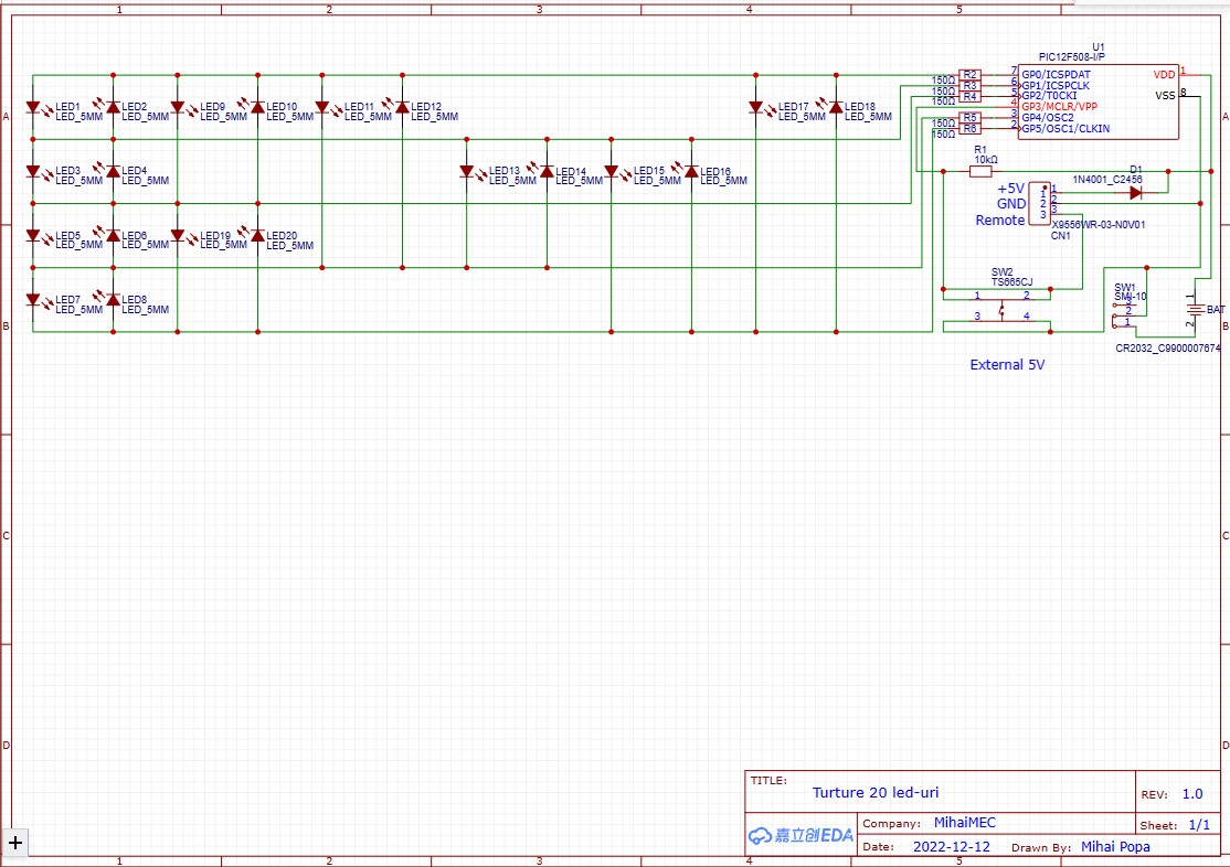
I chose a PIC12F series MCU, namely: PIC12F675. This MCU has 8 pins: 2 are used for power, one is Input-only (GP3, used also for Reset/MCLR) and another 5 are GPIO.
I chose to use these left 5 pins to "light up" 20 LEDs in a Charliplex configuration; in this way I managed to light up 20 LEDs, using the formula: No. of LEDs = No. of PINs * (No. of PINs - 1).
The electrical schematics is simple and is in the attachments section.
For developing the code anf flashing the MCU I used PicKit1. I know that is an old tool, but does its job well; so does MPLAB IDE V8.92
The code is well documented and anyone who opens it can broadly understand how it works.
In the attachments section you will find the two versions of the code: the original one, from 2022 and the updated one, from 2024. These two versions are tested in MPLAB IDE V8.92
On the top of the icicle, next to the MCU is an 3 pin connector. This connector is used for external power and to change "remotly" the LED program; "remotly" because the third pin from connector is connected to GP3 and near to power supply a button is connected between GND and GP3.
OBS: the project schematics and PCB was created based on other MCU: PIC12F508; after the PCB was ordered, I realized that I didn't have this PIC12f509 MCU to start creating the code; instead I had several PIC12F675. These MCUs have the same pinout, so I didn't modify the wiring diagram.
Important: if the icicle is powered by external power supply, then the onboard switch should be in Off position OR the battery should be disconnected!
Demonstration:Final setup:I connect them in paralel to an external 5V/3A power supply; then I soldered an switch near the power supply to change the icicles program. The button have the same functionality as "MODE" switch from each individual icicle (see the scematic).
In the code for this project I came across the fact that I cannot use GP3 to produce an interrupt of the type Interrupt -on-change, although this pin is marked as having this functionality in the PIC12F675 datasheet.
After long experiments and searches on the internet, I came to the conclusion that the only method of using this pin as an input is to repeatedly query it within the program. So, switching between the 3 display programs is done by holding down the button for a longer time (like a "long press").


Comments