The Atmel tinyAVR MCU's (ATtiny) are a series of chips optimized for applications requiring performance and/or power efficiency in a small package. These have internal clocks that runs at 8 MHz. They can also be clocked at 16 MHz and 20MHz using an external clock. There is a limitation though when using an external clock. Two of the already limited I/O pins are used leaving you with just three. Well, did you know you can run it at 16 MHz without using an external clock?
If you have used the ATtiny, you are probably familiar with how to use it through the Arduino IDE. If not, here is a quick overview.
The first step is to add a URL to the Additional Boards Manager option in Preferences. Select Preferences from the File menu and add the URL below to the text box. If there is more than one URL in the box, separate them with a comma.
https://raw.githubusercontent.com/damellis/attiny/ide-1.6.x-boards-manager/package_damellis_attiny_index.json
The second step is to install the board. In the Arduino IDE, click the Tools menu and then click Board. In the menu that appears, select Boards Manager. In the search text box type ATtiny to find the package for the this chip. Now, click the Install button to install the board.
After the install has completed, a new board option is available in the menu. The new board allows you to select an ATtiny45, ATtiny85, ATtiny44 or an ATtiny84. There is also a selection to run the clock at 1 MHz internal, 8 MHz internal, 8 MHz external, 16 MHz external or 20 MHz external.
To use an ATtiny, you will need to have a way to program the chip. It does not contain a bootloader or a USB interface. A programmer is needed to program these chips. I use the Tiny AVR Programmer from SparkFun which is designed specifically for the 8 pin chips. There are also a lot of articles on how to use another Arduino, such as an Uno, the program these MCU's.
Here are a few links to help:
- Programming ATtiny85 with Arduino Uno on Hackster.io
- Virtual Workshop: Program an ATTiny85 with Arduino
- Programming an ATtiny w/ Arduino 1.6 (or 1.0)
- Programming an ATtiny w/ Arduino 0022
Once setup, programming is easy through the IDE and works like any other AVR with some minor limitations. For example, there are a limited number of ports and less available RAM. Most of the chips do not have support for hardware serial. The I2C is also a bit different and does not work with the standard Wire library. Instead, you will need to use the TinyWireM and TinyWireS libraries.
One caveat of programming is, when using a brand new chip, or when changing the clock speed, you need to choose Burn bootloader from the menu. This will set the fuses on the chip so that it runs at the selected clock speed.
NOTE: be careful to NOT select external clock unless you have actually connected an external clock. Doing so will "somewhat" brick the chip. What I mean by somewhat is that, unless you have a high-voltage programmer to reset the fuses, or an external clock to connect to the chip, you will be unable to use it. If you are using, or plan to use a lot of these, it is a good idea to have high voltage programmer. I use the HV Resuce Sheild in the event I need to reset the fuses.
Adding the 16 MHz internal options requires updating the boards.txt file. To edit this file, you first need to open the folder where the file is located. To do this, select the Preferences option from the File menu. Near the bottom of the page is a link to the edit the preferences file directly. Clicking this link will open the folder where the board files are located. Click the link and open the folder.
After the folder has been opened, work your way into the following folders:
packages -> attiny -> hardware - > avr -> 1.0.1
NOTE: In Windows, run the following command in the Run window to quickly open the correct folder: %USERPROFILE%\AppData\Local\Arduino15\packages\attiny\hardware\avr\1.0.1
Locate the file named boards.txt and open it in a text editor. On Windows, I recommend using Notepad++. In the file, find the section that defines the 8 MHz (internal) menu option. This section is shown below.
attiny.menu.clock.internal8=8 MHz (internal)
attiny.menu.clock.internal8.bootloader.low_fuses=0xe2
attiny.menu.clock.internal8.bootloader.high_fuses=0xdf
attiny.menu.clock.internal8.bootloader.extended_fuses=0xff
attiny.menu.clock.internal8.build.f_cpu=8000000L
Paste the new menu definition (the one shown below) right after the 8 MHz (internal) section (the section shown above) and then save the file.
attiny.menu.clock.internal16=16 MHz (internal)
attiny.menu.clock.internal16.bootloader.low_fuses=0xf1
attiny.menu.clock.internal16.bootloader.high_fuses=0xdf
attiny.menu.clock.internal16.bootloader.extended_fuses=0xff
attiny.menu.clock.internal16.build.f_cpu=16000000L
If the Arduino IDE is open, you will need to close it and restart the application. Now, you will have the 16MHz (internal) option in your menu.
Remember, when using this option on a new chip or changing from another clock speed, use the Burn bootloader menu option. This option only needs to be run once.
VerificationHow do I know this chip is now running at the higher clock and is running properly? There were three checks that I performed to verify.
Measured the Clock
This Atmel chip supports an option, via a fuse setting, to output the clock on pin 3 (PORTB4, D4). Turning this on, I connected my oscilloscope to this pin and measured the frequency of the output. When the chip was set to 8 MHz I indeed measured the frequency at 8 MHz, and at 16 MHz it checked out at 16 MHz.
NOTE: Use this calculator to see the options for the fuses.
Square Wave Generator Output
What I really want to know is whether or not the chip is faster - able to perform more operations in a given time when running at 16 MHz verses running at 8 MHz. To measure this, I created a simple sketch that generated a square wave on pin 2 (PORTB3, D3) and measured the frequency.
Running the sketch on an ATtiny85 set at 8 MHz internal clock, the output frequency was measured at 2.028 MHz. The sketch running on the same chip clocked at 16 MHz produced a wave with a frequency of 4.048 Mhz.
The results from oscilloscope are shown in the mages below.
Sensor Test
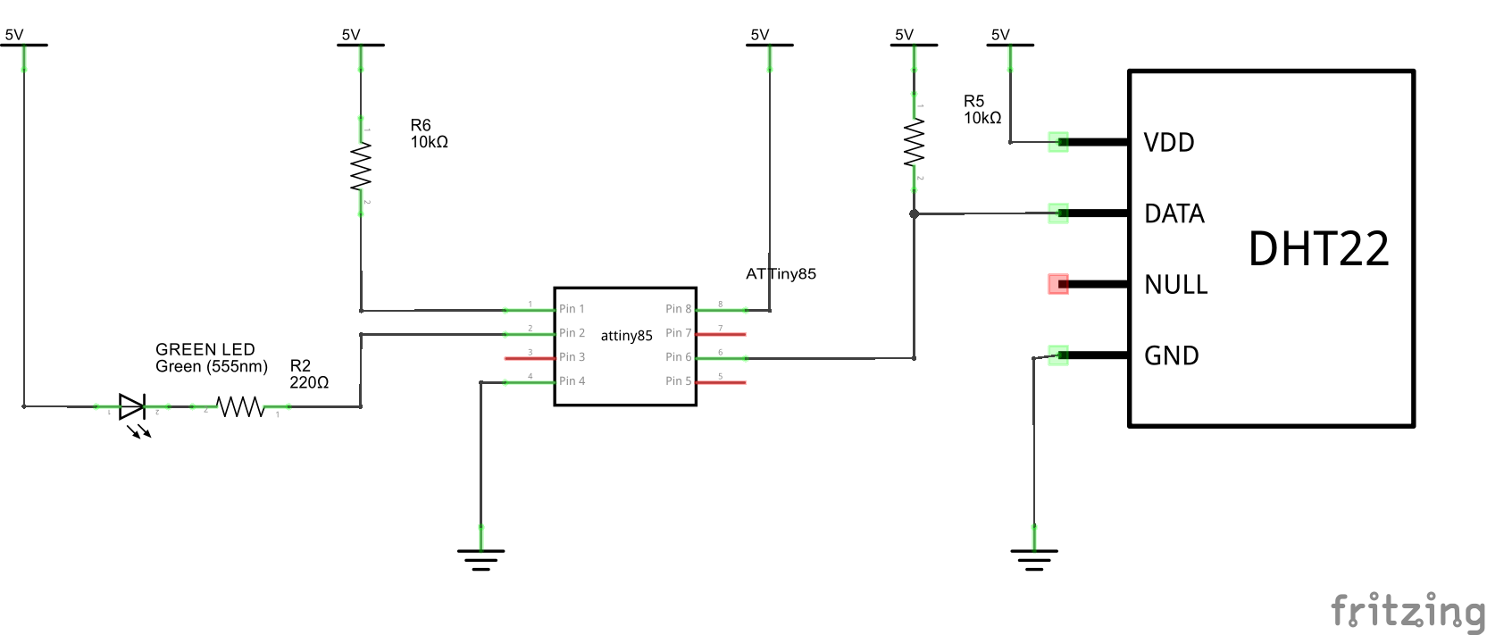
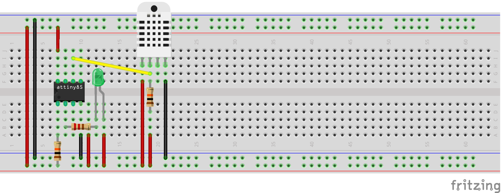
To ensure that the timing within code (code that depends on delay() or millis()) was not adversely aftected, I connected an ATtiny85 to a DHT22 temperature sensor. Anyone who has worked with this sensor knows how critical the timing is to get a reading from the sensor. I ran the Temperature.ino sketch on the same chip set at both 8 MHz and 16 MHz and did not encounter any issues reading the sensor.


_3u05Tpwasz.png?auto=compress%2Cformat&w=40&h=40&fit=fillmax&bg=fff&dpr=2)
Comments
Please log in or sign up to comment.