Microcontrollers require a programmer to install firmware on them. A programmer is a device, that when combined with software, loads firmware to the microcontroller. There are many programmers available. I won't go into to detail about them, but I will say that if you intend to do more than just tinker with microcontrollers, you will want to invest in a programmer.
The Arduino IDE allows firmware to be loaded directly through a serial port by communicating to a piece of software already loaded on the microcontroller. This special software preloaded to the microcontroller is called a bootloader.
For more information, see the article "Bootloader Development".
ATtiny85 MicrocontrollerIt is a good idea to have a basic understanding of the ATtiny85 microcontroller. In addition, there are many other ATtiny microcontrollers with varying features. Here is a summary of the ATtiny85 microcontroller features.
- 8 pins
- 8KB ISP flash memory
- 512-Byte EEPROM
- 512-Byte SRAM
- 6 general purpose I/O lines
- 32 general purpose working registers
- One 8-bit timer/counter with compare modes
- One 8-bit high speed timer/counter
- USI
- Internal and external Interrupts
- 4-channel 10-bit A/D converter
- Programmable watchdog timer with internal oscillator
- Three software selectable power saving modes
- DebugWIRE for on-chip debugging.
- The device achieves a throughput of 20 MIPS at 20 MHz and operates between 2.7-5.5 volts
For more information on this and other ATtiny microcontrollers, see Atmel's web site. This web site also contains detailed and summarized versions of the data sheets for each microcontroller.
Why Use a Bootloader?A bootloader makes prototyping easier because the code can be loaded to the microcontroller directly from the Arduino IDE using a basic serial connection.
When I program my ATtiny85, I have to pull it out of the circuit and insert it into my programmer. When it finishes loading the firmware, I pull it out of the programmer and then place it back into the circuit. I may repeat this process several times. At the very least, it gets old, but many times I have bent pins and had to straighten them out with a pair of needle-nose pliers.
With a bootloader, I can program my ATtiny85 while still connected to the circuit.
There are some occasions where the components in the circuit you are building may interfere with the upload process.Why Not Use a Bootloader?
The first, and primary reason, not to use a bootloader has to do with flash memory. Since a bootloader is firmware, it will use some of the flash memory on your microcontroller. The amount of memory it occupies may or may not be significant to you, but memory is tight, so pay attention to how much you are using.
The ATTiny85 has 8K (8,192 bytes) of flash memory for the code. The firmware will use 576 bytes leaving 7,616 bytes for your sketches (the firmware used in this project can be found at https://github.com/TCWORLD/ATTinyCore).
The second reason has to do with performance. A bootloader runs when the microcontroller is powered up or reset. This takes time due to the bootloader checking for an attempt to load new firmware. after the check, the bootloader starts the firmware you uploaded from the Arduino IDE. This process takes a few seconds to run resulting in delay before your firmware starts. Again, this may or may not be a significant issue for you, but you need to be aware of it.
I find the best balance is to use the bootloader while prototyping, and then, when creating the final project, burn your firmware to the microcontroller using a programmer.
Adding the Support to the IDEIf you are not familiar with adding a board to the Arduino IDE, the details are shown below. For additional information, see this article on Adafruit.
The first step is to add a URL to the Additional Boards Manager option in Preferences. Select Preferences from the File menu and add the URL shown below to the text box. If there is more than one URL in the box, separate them with a comma.
https://raw.githubusercontent.com/porrey/Snapduino/IDE/package_porrey_snapduino_index.json
In this project I am using the board definition for my Snapduino.
The second step is to install the board. In the Arduino IDE, click the Tools menu and then click Board. In the menu that appears, select Boards Manager. In the search text box type Snapduino to find the board package. Now click the Install button to install the board.
If you do not like the name of the board in the IDE (you are probably not using Snap Circuits), the name can be changed manually to anything you like. Follow the steps below to change the name of the board in the Arduino IDE menu.
- Click Preferences from the File menu.
- Click the link to customizer the preference file.
- Open the Packages folder.
- Open the Snapduino folder.
- Open the hardware folder.
- Open the AVR folder.
- Open the folder 1.0.1 folder.
- Open the boards.txt file in a text editor to change the board name.
- Edit the line 'snapduino.name=Snapduino' and change the name on the right side of the equals sign to something that suits you.
- Save the file.
- Open the platform.txt file in a text editor to change the category name.
- Edit the line 'name=Snap Circuits ' and change the name on the right side of the equals sign to something that suits you.
- Save the file.
- Close and re-open the Arduino IDE.
Uploading the bootloader to the microcontroller only has to be done once. Performing this step does require access to a programmer. The best programmer for the ATtiny85 (in my opinion) is the SparkFun Tiny AVR Programmer.
If you do not want to invest the money in one of these, it is possible to use another Arduino, such as the Uno, to program the microcontroller. Here are a couple of very useful resources that show how to do this.
- Programming ATtiny85 with Arduino Uno on Hackster.io
- Virtual Workshop: Program an ATTiny85 with Arduino
- Programming an ATtiny w/ Arduino 1.6 (or 1.0)
- Programming an ATtiny w/ Arduino 0022
If you have a programmer, place the ATtiny85 into the programmer and connect it to the USB port on your computer. Open the Arduino IDE and select the Snapduino board from the Tools menu. In the Programmer menu, under Tools, select the correct programmer. If you have the SparkFun AVR Tiny Programmer, choose USBtinyISP. Now click Burn Bootloader from the tools menu.
Pay close attention to the messages in the IDE when the process is underway. It is rare that it will fail, but it may happen. If the Arduino IDE reports that the process has failed, simply repeat it.
Always make note of the clock speed that was selected when you burn the bootloader and ensure that all sketches are loaded with the same selection. If you do not use the same selection, your sketches will work but your timing will be off.
The ATtiny85 microcontroller does not have a protected-bootloader section. This means it's possible to accidentally overwrite the bootloader on these chips. If this happen, just follow the steps to reload the bootloader.Connecting the FTDI Cable
We will need a way to communicate with the microcontroller form the Arduino IDE. The ATtiny85 does not have built-in USB support and we have not added this capability in our circuit. Instead we will use an FTDI Serial TTL-232 USB Cable.
The FTDI cable is a USB-to- Serial cable. It has a small microchip in the head of the cable that performs the conversion between the USB port and the Serial TTL required to program the microcontroller. This is a very poplar cable and contain be obtained from a variety of places. The one I am using in this project was purchased from Adafruit. I like this cable because it can be used in 3V3 and 5V circuits and always supplies 5V on the power line.
Most Arduino's and Arduino compatible boards have built in USB-to-Serial converters. Others have a firmware that can communicate over a USB connection. To see an ATtiny85 with a USB connection check out the Adafruit Trinket - Mini Microcontroller - 5V Logic.
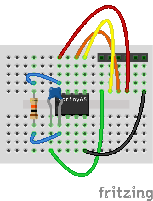
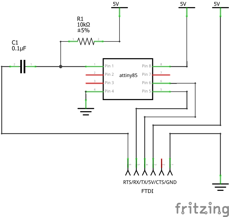
Place the ATtiny85 onto the breadboard with the 6-pin header and wire the circuit according to the diagram included in the project below.
The circuit provides basic support to program the microcontroller. These components will be included in all of your circuits. The 10K Ω resistor is used as a pull-up resistor to keep the reset pin high. The .1 µF capacitor is connected to the RTS pin on the FTDI cable to allow the Arduino IDE to automatically reset the ATtiny85 microcontroller while programming.
Tune the BootloaderThe bootloader being used for the ATtiny85 requires a one-time tuning process to allow it to synchronize with the serial interface. This step ensures that the uploading process will be consistent.
Open the Arduino IDE and select the Serial Monitor from the Tools menu. When the window appears, set the baud rate from the drop down, located at the bottom right corner of the screen, to 9600 if you burned the bootloader at 8MHz, or choose 19200 if you used 16MHz.
A message will appear from the device asking you to send an 'x' slowly until the bootloader has completed the tuning process. Simply place and 'x' in text box at the top of the window and press send. Repeat this until the bootloader indicates it has completed. Once you have completed this step, you will not need to repeat it again unless you burn the bootloader again.
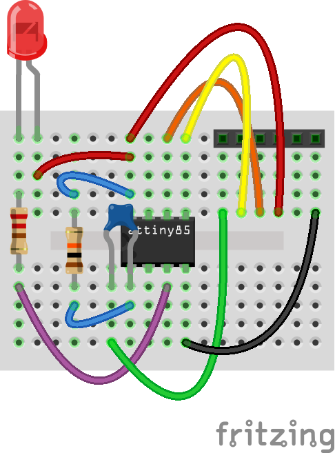
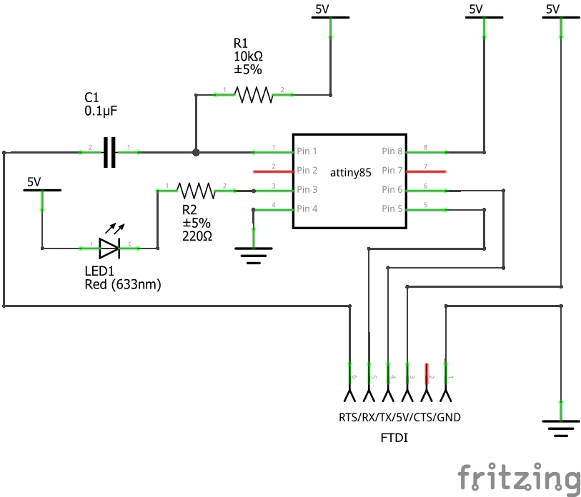
Add the LED and the 220 Ω resistor to the breadboard as shown in the attached diagram. Download the Blinking LED Code located near the bottom of the project and open it in your Arduino IDE. Select the Snapduino and the processor speed you wish to run (only use 16 MHz when running at 5V). Ensure the correct serial port for your FTDI cable is selected and click Upload.
When the sketch finishes uploading, your LED will begin to blink.







_3u05Tpwasz.png?auto=compress%2Cformat&w=40&h=40&fit=fillmax&bg=fff&dpr=2)
Comments
Please log in or sign up to comment.