Snap Circuits® makes learning electronics easy and fun! Learn how to use integrate Snap Circuits® with your hardware. Fun for kids!
Introduction ProjectIf you have not completed the introduction please go to the Snap Circuits - Introduction project. This project also contains a complete index of Snap Circuit projects.
Let's Get StartedProject ObjectiveTo show how to use an Arduino sketch to blink an LED.
Building the CircuitThe minimum set requirement for this project is SC-100.
Open the PDF below and follow the directions. The PDF file can also be found in the GitHub repository.
Here are images of the components that you will use to build the circuit.
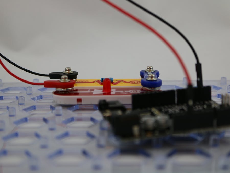
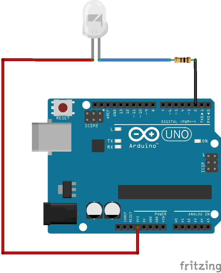
Here are images of the completed circuit.
The attachment below contain the sketch for this project. Click the link below and save this to your computer.
After the file has been downloaded you can either double-click it to open it in the IDE or you can open the Arduino IDE and choose File->Open from the menu and browse to this file.
When you open this downloaded sketch in the Arduino IDE it will prompt you to move the file into a sketch folder. Choose OK to let it create this for you. If you are familiar with using the IDE you can also place these in your sketch path.
At this point the circuit is built, the Arduino IDE is installed, your board and port are configured and the sketch has been downloaded and loaded in the IDE. Now it is time to upload the sketch to the Arduino. Ensure that your USB plug is connected to your computer and then choose Upload from the File menu. When it has completed loading the LED should begin to flash every second.
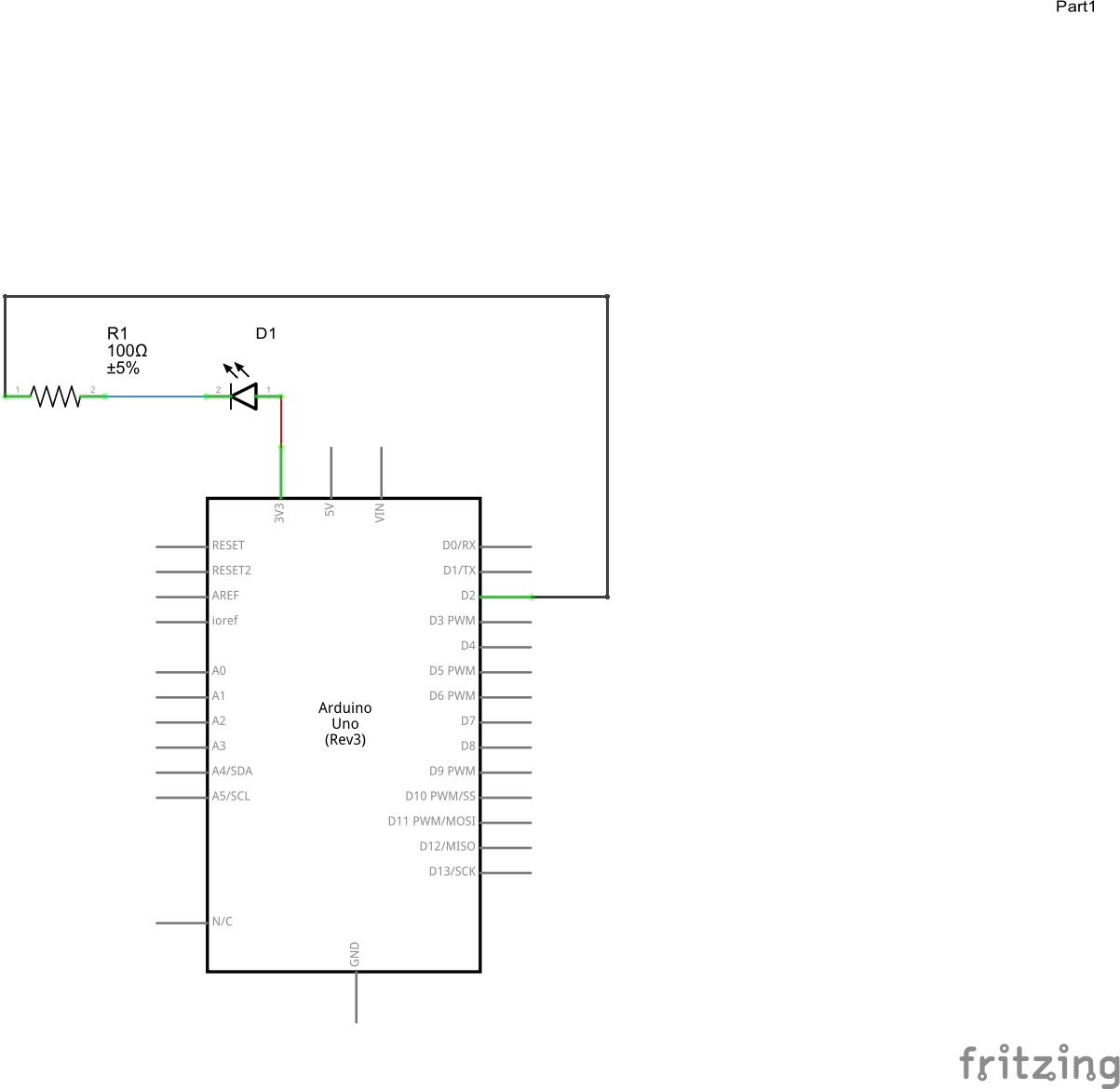
How this WorksThe CircuitThe resistor R1 in the component helps restrict the amount of current that flows into the LED and helps to prevent the LED from burning out by getting too much current.
The LED D1 has a anode and a cathode. The anode end of the LED (this is the end marked +) is connected to the 3.3V (three point three volt) source on the Arduino. The cathode end of the LED is connected to pin 2 on the Arduino through the resistor R1. An LED can only allow current to pass in on direction, and when the current passes in the correct direction, it will produce light.
When the output voltage of pin 2 is set to HIGH (5.0V) the LED is off because the potential difference between these two pins is less than -1.7V. Note the voltage is negative which means it reversed direction. Since the LED will not light up when the current moves through in the wrong direction, this has the effect of turning it off.
When the output of pin 2 is set to LOW (0.0V) the potential difference is 3.3V and current moves through the LED and it lights up.
Why use the 3.3V pin and not the 5V pin? If we used the 5V pin on the Arduino instead of the 3.3V pin we would drive about 25 mA of current through the LED. This is the upper limit of this particular LED. We want to be careful not to burn the LED out so using 3.3V is safer.The Software
All Arduino sketches have a Setup function and a Loop function. The setup function is executed or run once when the Arduino is powered up or any time the reset button is pressed. The loop function is called repeatedly for forever.
In this sketch, the setup function is used to tell the Arduino which pin we want to use and what we want to do with it. In the sketch for this project we are setting the pin using a constant called PIN_NUMBER which has a defined value of 2. We are telling the Arduino that we would like to use pin 2 as an output pin, that is , we will specify the value of the pin in our application. The value of the pin can be HIGH (5.0V) or LOW (0.0v).
#define LED_PIN 2

// ***
// *** The setup function runs once when you press
// *** reset or power the board.
// ***
void setup()
{
 // ***
 // *** Initialize the digital pin for output.
 // ***
 pinMode(LED_PIN, OUTPUT);
}
In the loop function we will vary the value of the output pin and have the application delay for a period of time between each change. This gives the appearance of a flashing LED. The rate at which it flashes depends on the amount of time in the delay. The delay is specified in a constant called DELAY_TIME and is set to a value of 1000 milliseconds or 1 second.
#define DELAY_TIME 1000
In the loop, the LED is first turned on by setting the pin output to LOW. The application then delays for 1 second. This is followed by the application setting the pin output to HIGH and then delaying again for another one second.
// ***
// *** The loop function runs over
// *** and over again forever.
// ***
void loop()
{
 // ***
 // *** Turn the LED ON. Since we have connected
 // *** the LED to the 3.3v pin we must set our
 // *** GPIO pin to LOW to light the LED.
 // ***
 digitalWrite(LED_PIN, LOW);
 // ***
 // *** Pause
 // ***
 delay(DELAY_TIME);
 // ***
 // *** Turn the LED off. Since we have connected
 // *** the LED to the 3.3v pin we must set our
 // *** GPIO pin to HIGH to turn the LED off.
 // ***
 digitalWrite(LED_PIN, HIGH);
 // ***
 // *** Pause
 // ***
 delay(DELAY_TIME);
}
- LED's only allow current to flow in one direction. Remove the LED from the circuit and turn it around. Try running the software again. What happened? If you look very close it is lighting up just a little bit. This is because we are still applying about 1.5V to the LED which is barley enough to get any light out of it. If we switched the red pin from the 3.3V pin to the 5V pin would it light up more or less? It would be less because the voltage in the reverse direction would be 0V.
- The LED in the circuit will remain on for 1 second and then remain off for one second. Change the value in the sketch called
DELAY_TIMEand see what happens. How can you make the LED flash faster? How can you make the LED flash slower? - The black wire in the circuit is connected to Pin 2 on the Arduino. Look at the software and try to determine how to connect this to another pin. For example, if you were to connect the black wire to pin 1 on the Arduino what would you need to change in the software? Move the black wire to pin 1. What happened? The LED stopped flashing. Try changing the software and upload it again so that the LED will continue to flash as it did before (hint: the value of one of the constants needs to be changed)
- [This requires SC-300 set] The resistor in this circuit helps to protect the LED from getting too much current. If your Snap Circuit kits contains other resistors try changing the resistor value and see what happens. Describe what happens when the R1 is changed to R2 (1K)? The 'K' on this component means times 1000. After you changed R1 to R2 you should have noticed the LED is not as bright. Can you guess why? You will learn more about this is future projects.
- Press the Reset button on the Arduino. What happened? The LED stopped flashing for a few seconds and then started flashing again. The reset buttons stops and restarts the application that is currently running. It does not, however, erase the application. Once you load an application onto the Arduino it will remain there until you replace it with another program. Even if you pull the power (unplug the USB) the application will still be there when you turn it back on.
- Is it possible to have the LED stay on for a different amount of time than it is off? For example, how can you make the LED remain on for 1 second and remain off for 2 seconds? (hint: add a second constant for delay time with a new name and use it in the second delay() statement).
TIP:
If you would like to have your Arduino "do nothing" when it is powered on you can load the BareMinimum sketch. When my son first built this project I had already loaded the sketch on the Arduino. As soon as he plugged it in it started to flash. This took away some excitement. I then loaded the BareMinimum sketch (found under the basic examples) and then let him upload the sketch for this project himself. I found that he loved not only building the circuit but uploading the application watching it start was even more exciting for him. It is all part of the fun!
Keep this circuit for the Push Button Monitor project!


Comments