


Hardware components | ||||||
 |
| × | 1 | |||
 |
| × | 1 | |||
 |
| × | 1 | |||
Software apps and online services | ||||||
 |
| |||||
Snap Circuits® makes learning electronics easy and fun! Learn how to use integrate Snap Circuits® with your hardware. Fun for kids!
Introduction ProjectIf you have not completed the introduction please go to the Snap Circuits - Introduction project. This project also contains a complete index of Snap Circuit projects.
Let's Get StartedProject ObjectiveDemonstrate how to change the intensity of an LED to make it appear to "breath" or "glow".
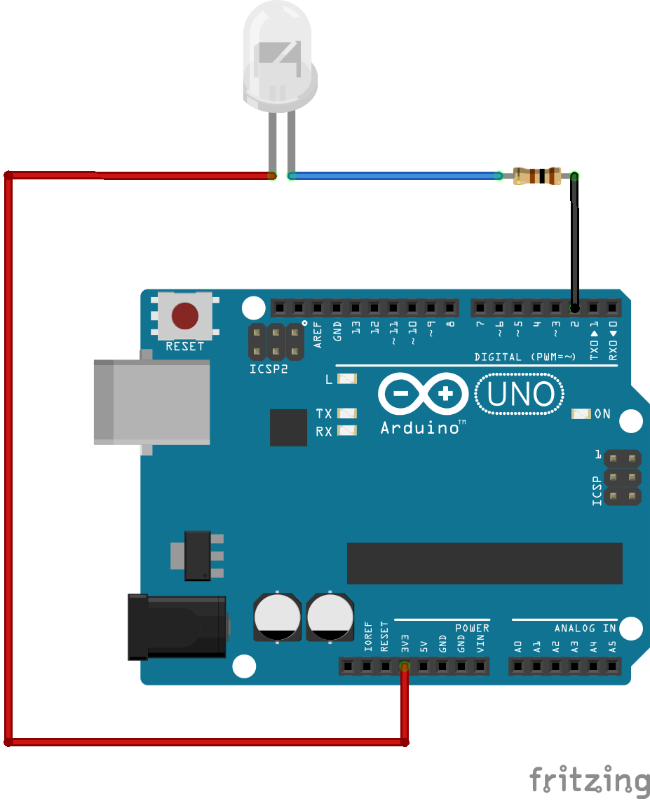
Building the CircuitThe minimum set requirement for this project is SC-100.
// ***
// *** Parameters for "breathing"
// ***
#define MINIMUM_ANALOG 0
#define MAXIMUM_ANALOG 220
#define STEP 1
#define DELAY 7
// ***
// *** Parameters for "breathing"
// ***
#define MINIMUM_ANALOG 0
#define MAXIMUM_ANALOG 220
#define STEP 1
// ***
// *** Parameters for "breathing"
// ***
#define MINIMUM_ANALOG 0
#define MAXIMUM_ANALOG 220
#define STEP 1
// ***
// *** Parameters for "breathing"
// ***
#define MINIMUM_ANALOG 0
#define MAXIMUM_ANALOG 220
#define STEP 1
Open the PDF below and follow the directions. The PDF file can also be found in the GitHub repository.
Here are images of the components that you will use to build the circuit.
The attachment below contain the sketch for this project. Click the link below and save this to your computer.
Load this sketch into the Arduino IDE in the same manner as in the Blinking LED project. After it is loaded compile and run it. The sketch for this project will write output to the serial port so you will need to open the Serial Monitor from the Tools menu (you can press Ctrl-Shift M).
The LED (Light Emitting Diode) is a device that can emit a bright light at a very low amount of power. With the number of portable electronic devices running on batteries it is important to design circuits that use as little power as possible to accomplish their purpose.
In general, an LED's intensity (or brightness) is controlled by the amount of current it draws. Thee are two ways to control the current flow into an LED. The first is with a resistor. A typical LED circuit has what is called a current limiting resistor. This is nothing more than a resistor in series with the LED to prevent the LED from drawing too much power. The second way to control current is with the voltage applied. The higher the voltage the higher the current that will flow through it. LED's have limits though and to much current or voltage) will destroy the LED.
If we want to make our LED look dimmer or brighter we can try to control the current flowing through it, however, there is a problem with this approach. More current means more power and we have already decided to use an LED over a light bulb because of its low power consumption.
There is a way to control the apparent brightness of an LED without trying to control the amount of current flowing though it. The technique is called pulse width modulation (PWM). To find out more about pulse width modulation see my project called "Many Colors with Variable RGB LED". This project references a good article describing PWM called "PWM - What is it, How does it work and how to detect it".
The basic principle is that the LED is pulsed at high frequencies so that the amount of time the LED is "on" verses the amount of time it is "off" is changed. This is detected by your eye as varying levels of brightness.
In the project I references, I show how to create a software based PWM to control an RGB LED. This type of LED has three colors that all need to be controlled independently. The Raspberry Pi (used in that project) on has one hardware based PWM pin which required the RGB LED to be controlled using software.
In this project I am using a hardware based PWM on the Arduino to control a single color LED. Since the Arduino has multiple hardware PWM pins this can be done with simple modifications to the sketch for this project.
The circuit in this project is identical to the Blinking LED project.
The SoftwareThe main difference between the sketch in this project and the sketch in the Blinking LED project is that instead of using digitalWrite on the output pin we use analogWrite. This function directs the output to be a PWM signal and allows the frequency of the PWM to be specified.
The software will loop from a low frequency to a higher frequency and then back down to increase and decrease the brightness of the LED. The overall effect is controlled by these lines of code:
// ***
// *** Parameters for "breathing"
// ***
#define MINIMUM_ANALOG 0
#define MAXIMUM_ANALOG 220
#define STEP 1
- Vary the parameters above to see the different affects on the LED.


Comments
Please log in or sign up to comment.