


Hardware components | ||||||
 |
| × | 1 | |||
 |
| × | 1 | |||
 |
| × | 1 | |||
Software apps and online services | ||||||
 |
| |||||
Hand tools and fabrication machines | ||||||
| ||||||
Follow the Snap Circuits platform!
OverviewWhat Are Snap Circuits?
Snap Circuits® makes learning electronics easy and fun! Learn how to use integrate Snap Circuits® with your hardware. Fun for kids!
Introduction Project
If you have not completed the introductory project please go to Snap Circuits - Introduction.
Let's Get StartedProject Objective
To show how to use an Arduino sketch to measure light using a photoresistor.
Building the Circuit
The minimum set requirement for this project is SC-100.
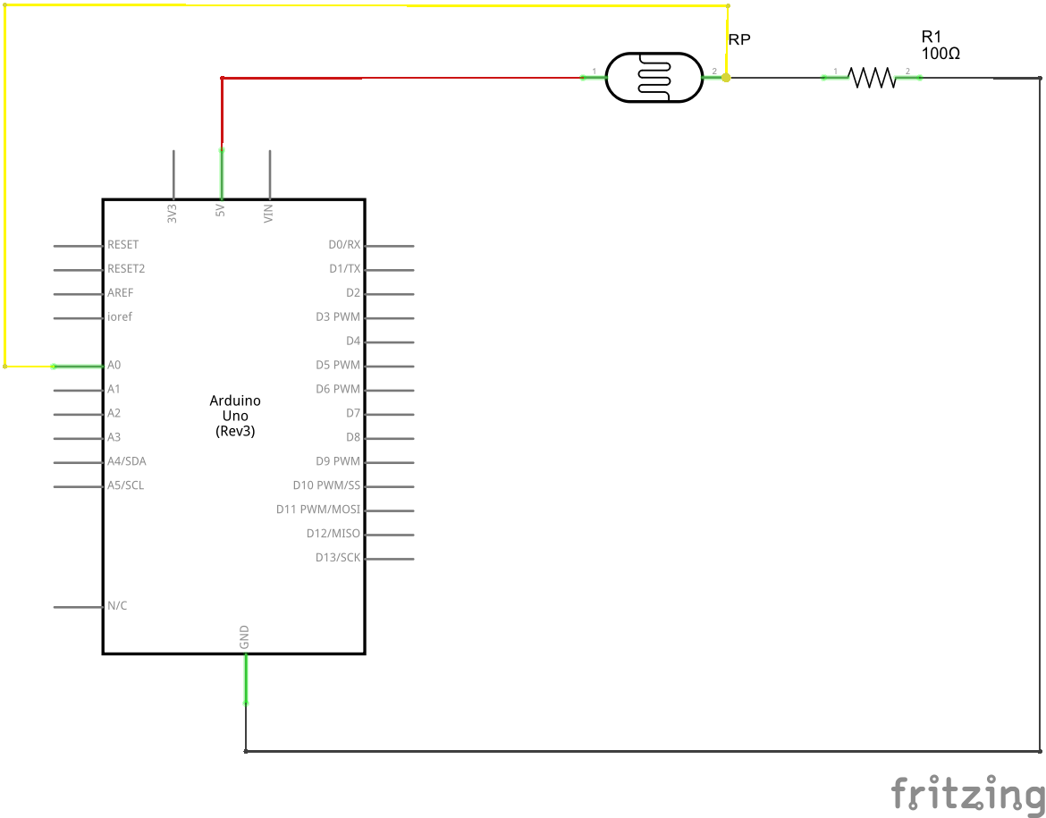
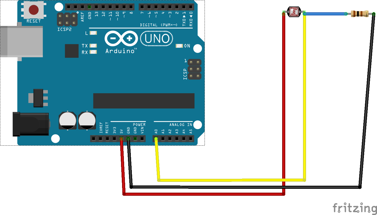
Build the following circuit:
Click the link below to download a PDF containing the circuit diagram and instructions to build it (the PDF file can also be found in the GitHub repository).
Download Circuit Diagram and Instructions
Here are images of the components that you will use to build the circuit.
Loading the Sketch
The attachment below contain the sketch for this project. Click the link below and save this to your computer.
(you may need to right-click and choose Download or Save Target As)
Load this sketch into the Arduino IDE in the same manner as in the Blinking LED project. After it is loaded compile and run it. The sketch for this project will write output to the serial port so you will need to open the Serial Monitor from the Tools menu (you can press Ctrl-Shift M).
The Circuit
The circuit in this project is a simple voltage divider. A voltage divider takes a voltage and divides it or reduces it. This is done using two resistors in series and measuring the voltage from the point between the two resistors. In this particular circuit, one of the resistors is a photoresistor.
A photoresistor behaves like a resistor except that the value of the resistor changes with the amount of light.
The photoresistor is referred to by other names such as photocell or light dependent resistor (LDR). When there is no light the resistance on a photoresistor can be several mega-ohms (MΩ). When light hits the cell the value of the resistance drops proportional to the amount of light. Photoresistors come in varying sizes based on the resistance value in full light. The RP module that comes with Snap Circuits is about 1000 Ω (1 KΩ) in full light and can be has high a 3 to 4 MΩ in total darkness.
NOTE: Photoresistors are not used for making precise measurements of light. The resistance value is proportional to light but is not typically linear. These devices are typically used to detect light in simple circuits where a precise measurement is not required. I call this project "Measuring Light" because we are still measuring light, just not in a precise manner or in a manner that makes sense in something like a photography application.
When the light across our component varies the voltage output at Vout will change proportionally. If we measure this voltage as it changes we can detect changes in the amount of light presence in our environment. In the circuit for this project, we will connect an analog pin from the Arduino to Vout and measure the voltage.
Derived using Ohm's Law (V = IR), the voltage at this point will can be calculated using the equation shown above. In the case of this project, we will know Vout because we will be directly measuring it. What we would really like to know is the value of R1 as the light changes (remember R1 in our circuit is the photoresistor).
The Software
The sketch in this project uses the equations shown above to calculate the value of the photoresistor by measuring the voltage at Vout via an analog pin. The calculated value of R1 is displayed in the Serial Monitor.
The values of R2 and Vin are defined in the lines of code as shown below:
#define R2 100.
#define VIN 5.0
In the loop() function the analog pin is read every 500 ms and the value of R1 is displayed if it changes.
int adc = analogRead(_analogPin);
The source used the line of code
r2 * (( vin / vout) - 1)
to calculate the value of R1 where Vout is determined by
(adc / MAX_ADC) * vin
- If you have the SC-300 set you can try different size resistors. Try to do this. Note the code has the other Snap Circuits resistor values defined. Remember when you change the resistor to update the code. Using Ohm's Law try to predict what will change with varying resistor values.
- Note that this circuit can also be used with a 3.3V source. Using a flashlight shined directly into the component RP, record the value of the resistor from the Serial Monitor. Now try connecting the red wire in the circuit to the 3.3V pin on the Arduino. Is the resistor value the same with? It should no be. The source code also needs to be changed. Try to determine what needs to be changed in the code and try it again. Was the reading closer to the original value? It should have been. Ohm's Law still works when the value on Vin is changed.


Comments
Please log in or sign up to comment.