Follow the Snap Circuits platform!
Overview
What Are Snap Circuits?
Snap Circuits® makes learning electronics easy and fun! Learn how to use integrate Snap Circuits® with your hardware. Fun for kids!
Introduction Project
If you have not completed the introduction please go to the Snap Circuits - Introduction project. This project also contains a complete index of Snap Circuit projects.
Let's Get Started
Project Objective
To show how to use an Arduino sketch to monitor a push button.
Building the Circuit
The minimum set requirement for this project is SC-300.
Open the PDF below and follow the directions. The PDF file can also be found in the GitHub repository.
Here are images of the components that you will use to build the circuit.
Completed Circuit
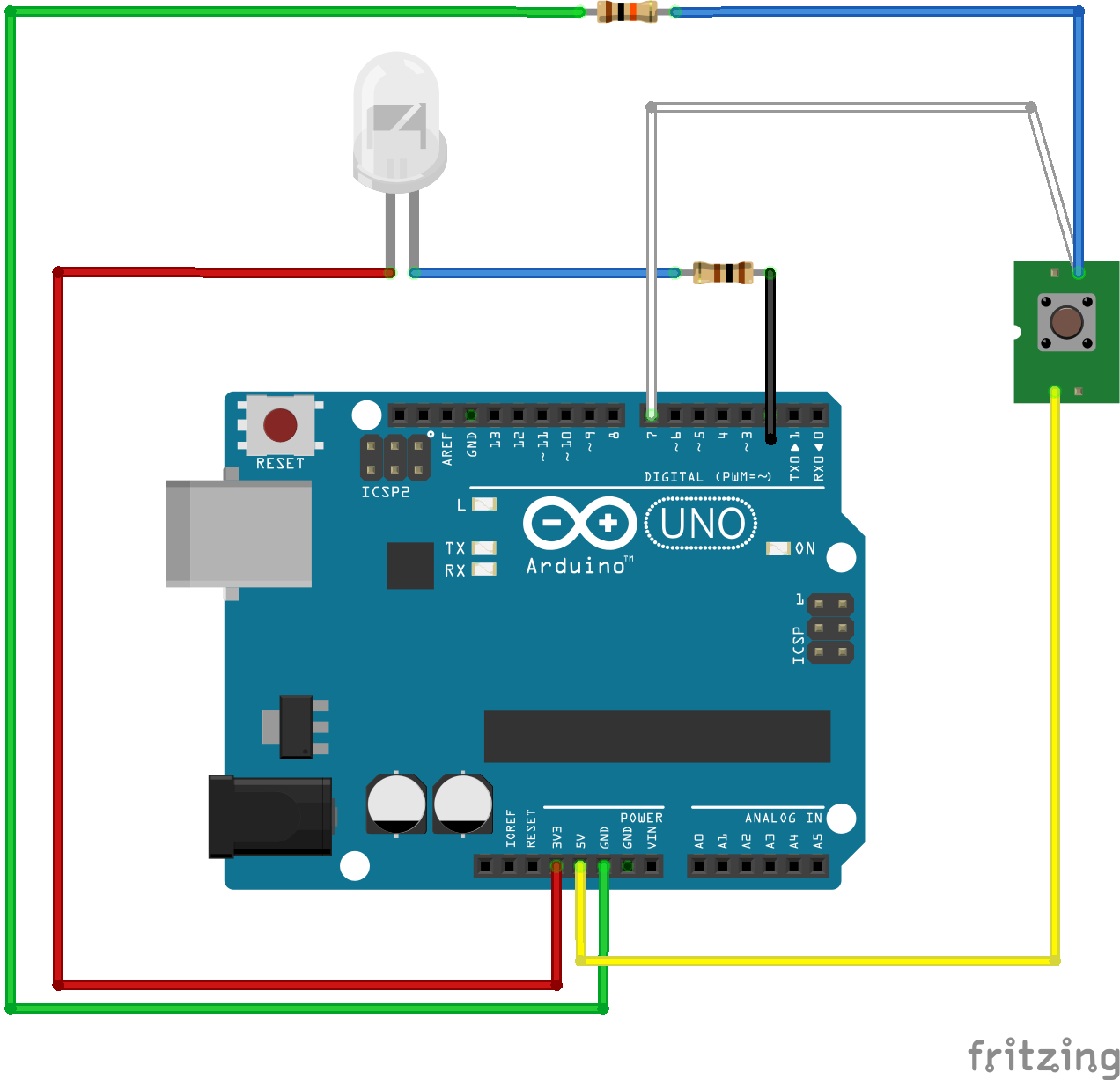
Here are images of the completed circuit.
I built a a wooden box to hold the Snap Circuits board and the Arduino. I purchased some wood from a local hobby shop, cut the pieces and glued them into place. If you are interested in the details let me know and I will post them.
Loading the Sketch
The attachment below contain the sketch for this project. Click the link below and save this to your computer.
Load this sketch into the Arduino IDE in the same manner as the Blinking LED Project. After it is loaded compile and run it. The sketch for this project will write output to the serial port so you will need to open the Serial Monitor from the Tools menu (you can press Ctrl-Shift M).
How this Works
The Circuit
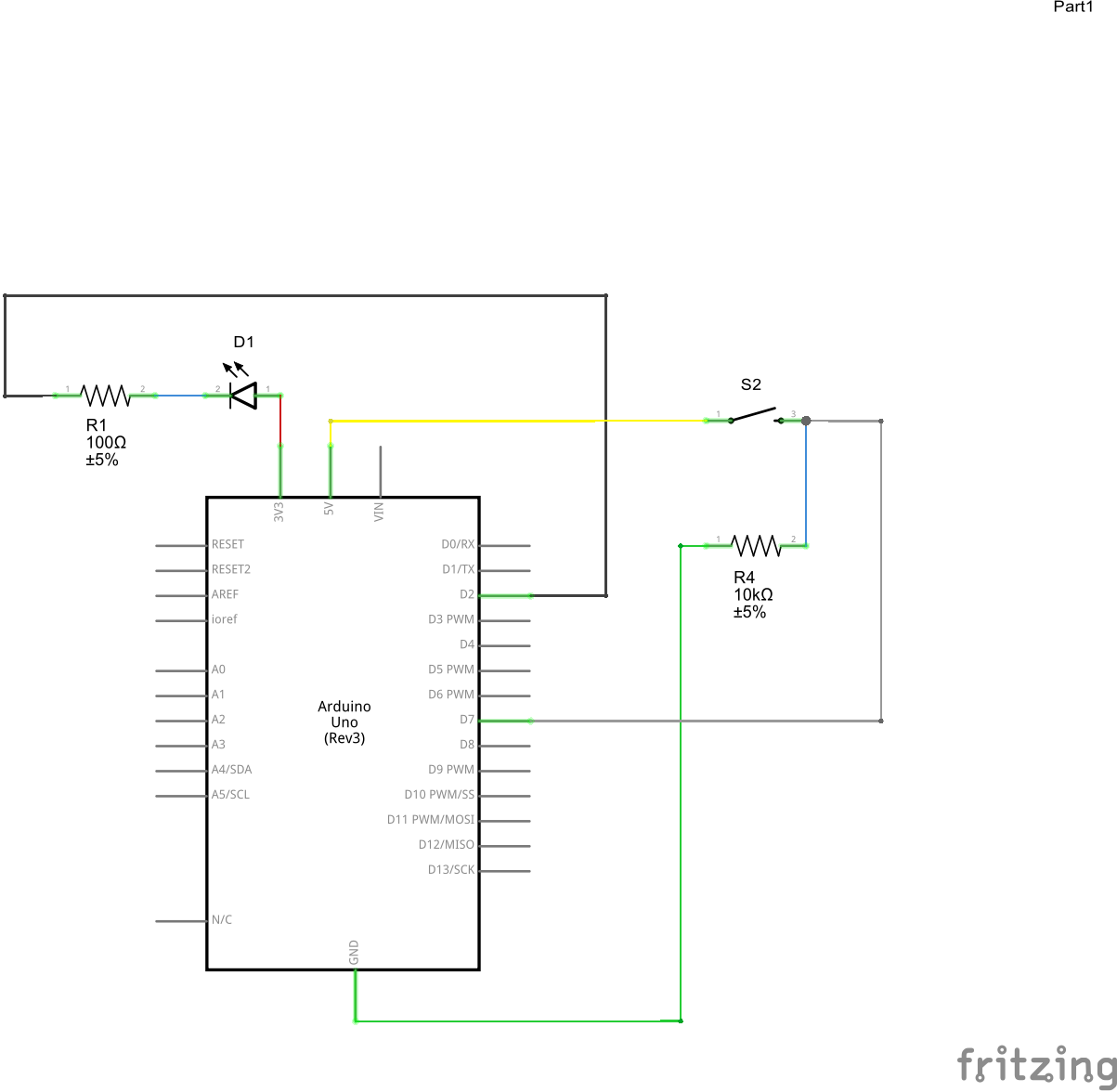
The digital pins on the Arduino can be configured to be output or input pins. In project one we set the mode to output so we could change the state of an LED. The switch and the resistor added to the circuit allow us to toggle the state of a second pin on the Arduino configured for input; that is, we are going to read whether the pin is HIGH or LOW.
To achieve HIGH or LOW we are connecting one end of our switch to to the 5V source on the Arduino. We could connect the other to one of the digital pins but this would cause us to have a "floating" state when the switch is open. A floating state means that when we read the pin in our software we will get random results. We want to "lock" down the value so that it is either HIGH or LOW. We do this by adding the 10K resistor into the circuit. One end of this resistor is connected to ground while the other end is connected to the switch and to the digital pin. When the switch is open the digital pin is connected to ground through the resistor and the reading on this pin will be LOW. When the switch is closed (by pushing it down) the switch connects the digital pin directly to 5V and the reading on the pin is HIGH.
The Software
In the Setup function of the sketch the serial output is first setup so that we can get some feedback while the application is running. Open the Serial Monitor to see the output while the application is running. Next the digital pin is setup for input and the current values is read to initialize the Loop function.
void setup(){ // *** // *** Display the pin number // *** Serial.begin(115200); Serial.print("Monitoring push button on pin "); Serial.println(BUTTON_PIN);
// *** // *** Initialize the digital pin for input. // *** pinMode(BUTTON_PIN, INPUT);
// *** // *** Get the current value of the pin // *** _previousValue = digitalRead(BUTTON_PIN);}
In the Loop function we are monitoring the digital pin by reading the value and checking it against the previous value. If the current value of the digital pin different than the previous version the action is displayed. When the current value is HIGH the button is closed or pushed down. If the current value is LOW then the button is open or has been released.
// ***// *** Read the current value from the pin// ***int currentValue = digitalRead(BUTTON_PIN);
At the bottom of the loop is a delay statement that delays the next read. This done as a simple debounce feature.
delay(DEBOUNCE_TIME);
What is debounce? A switch when pressed will generate false open and close transitions while the internals of switch are coming into contact with each other to close the circuit or while they are separating to open the circuit. There are many ways to account for this in software and in the hardware. For this project, I am using a simple delay to eliminate the extra transitions.
Read more about debounce:
The image below demonstrates the output from the application.
Things to Try
- It is good to see what happens when the input on the digital pin "floats". Un-snap the green wire and put it aside where it will not make contact with the circuit. Now start the application and repeatedly push and release the button. What to you notice. Some times the application behaves properly and some time the switch events are not detected. Now put the green back on and try again. Everything should work fine now.
- In the application the default debounce time is set to 100ms. Set this value to 0 and try the it again. What happens? Now experiment with various values to see how it changes the behavior of the application.


Comments
Please log in or sign up to comment.