Follow the Snap Circuits platform!
Overview
What Are Snap Circuits?
Snap Circuits® makes learning electronics easy and fun! Learn how to use integrate Snap Circuits® with your hardware. Fun for kids!
Introduction Project
If you have not completed the introduction please go to the Snap Circuits - Introduction project. This project also contains a complete index of Snap Circuit projects.
Let's Get Started
Project Objective
Count from 0 to 9 on a seven segment display.
Building the Circuit
The minimum set requirement for this project is SC-500.
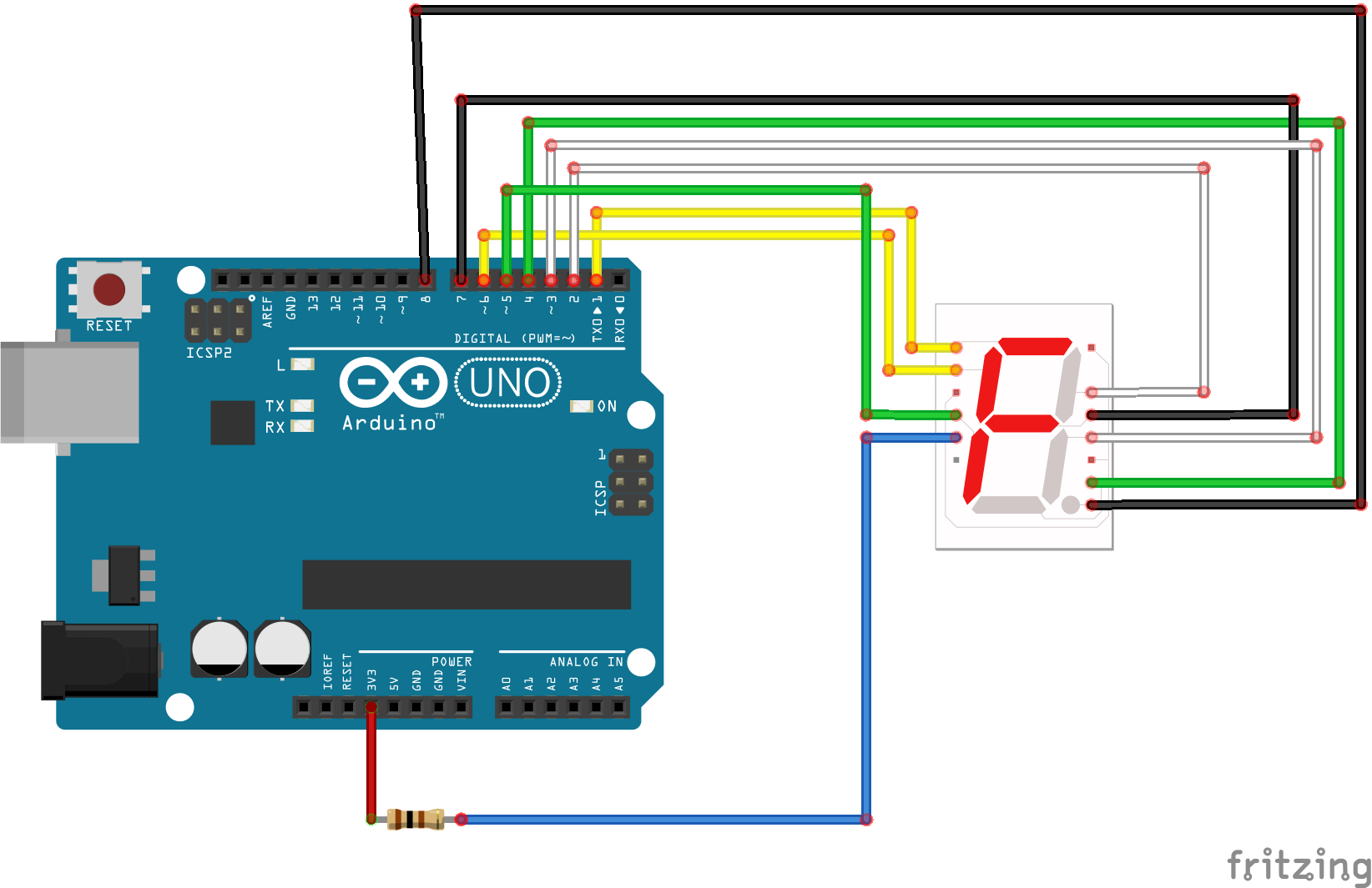
Open the PDF below and follow the directions. The PDF file can also be found in the GitHub repository.
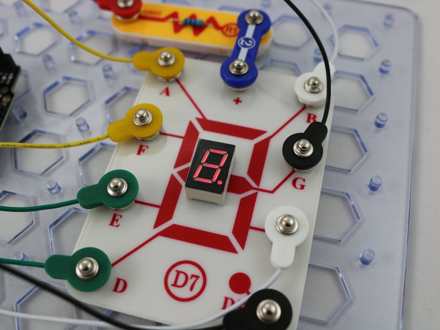
Here are images of the components that you will use to build the circuit.
Loading the Sketch
The attachment below contain the sketch for this project. Click the link below and save this to your computer.
Load this sketch into the Arduino IDE in the same manner as in the Blinking LED project.
After it is loaded compile and run it. The sketch for this project will
write output to the serial port so you will need to open the Serial Monitor from the Tools menu (you can press Ctrl-Shift M).
How this Works
The Circuit
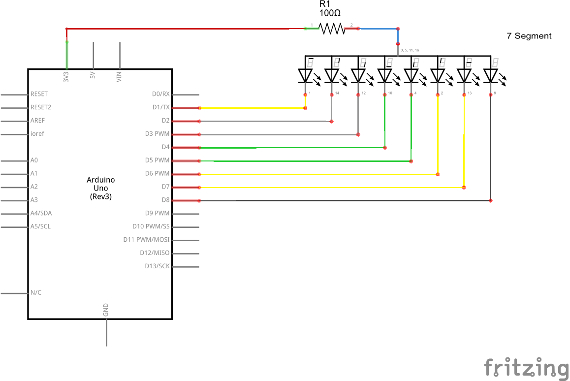
This circuit is similar to the basic LED circuit except that there are seven LED's. These LED's just happen to be arranged in a specific pattern and contained within a single component. If the LED's are turned on randomly they do not make much sense but when they are turned on in patterns they can create discernable numbers and even some letters.
The LED's in the component are called segments. Each segment has a label from A to G and a period labeled DP.
The Software
Most of the work is done in the software. First the Arduino pins are mapped to their corresponding labels in these lines of code:
#define PIN_A 1#define PIN_B 2#define PIN_C 3#define PIN_D 4#define PIN_E 5#define PIN_F 6#define PIN_G 7#define PIN_DP 8
Next there is a two dimensional array called FONT. The first dimension defines each character. In this program there are 23 characters defined. The second dimension of the array corresponds to each segment that is either turned on (LOW) or turned off (HIGH) for that character. There are two special characters defined. The first is call ALL_ON and in this character all the LED's are on. This is used to test the connections and the LED to ensure it is connected properly and working. The second special character is called ALL_OFF. This ones simply turns all of the LED's off.
#define ALL_ON 21#define ALL_OFF 22
In the setup() function the output pins are initialized for output. In addition, the ALL_ON character is displayed momentarily and then the ALL_OFF character is displayed.
In the loop() function each character is for one second. This can be changed.
#define DELAY 1000
Things to Try
- Try to add an additional character and have it displayed in the loop. For example, the letter 'L' can be displayed on this component. Add a new character to the array and set the individual pin values (LOW or HIGH) to display the 'L'. HINT 1: Copy and paste one of the other characters and modify it. Pick one close to L. HINT 2: The value of CHARACTER_COUNT must be updated too.


Comments
Please log in or sign up to comment.