Follow the Snap Circuits platform!
OverviewWhat Are Snap Circuits?
Snap Circuits makes learning electronics easy and fun! Learn how to integrate Snap Circuits with your hardware. Fun for Kids!
Introductory Project
If you have not completed the introductory project, please see Snap Circuits - Introduction. This project also contains a complete index of Snap Circuit projects.
Let's Get StartedProject Objective
This experiment will use the Snapduino to create device that can test the condition of a AA battery.
Building the Circuit
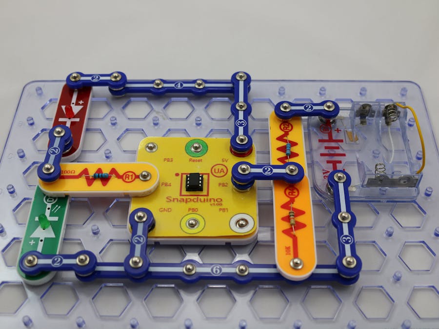
The minimum set requirement for this project is SC-300 and the Snapduino. Build the following circuit by following the directions in the PDF file:
Scroll down to see and download the PDF file containing complete build instructions (the PDF file can also be found in the GitHub repository).
Completed CircuitThe Circuit
The circuit is comprised of two parts. The first part uses the battery holder for the target battery tp be tested. Since the battery holder will hold two batteries, and we are focused on testing just one battery, the second battery position is shorted with a wire or paperclip. The two terminals of the battery holder are connected to a voltage divider circuit. A Snapduino analog pin is used to measure the voltage from the center of the divider and ground.
The second part of the circuit is the dual LED circuit. This is the same circuit from the Snapduino Dual LED Single Pin project and is used to indicate whether the battery is good or bad.
The Software
The sketch will read the analog pin voltage and convert it to a battery voltage uses the known resistor values and the voltage divider equations. The test of whether or not the battery is good or bad is subjective. The sketch determines the battery is good if the voltage is above a certain level. This can obviously be adjusted or changed all together.


Comments
Please log in or sign up to comment.