Follow the Snap Circuits platform!
OverviewWhat Are Snap Circuits?
Snap Circuits makes learning electtronics easy and fun! Learn how to integrate Snap Circuits with your hardware. Fun for Kids!
Introductory Project
If you have not completed the introductory project please see Snap Circuits - Introduction. This project also contains a complete index of Snap Circuit projects.
Let's Get StartedProject Objective
Using the Arduino, monitor a button, that when pressed, will count down 3 seconds by flashing the red LED and launch the fan. The green LED will turn on when the fan is launched.
Building the Circuit
The minimum set requirement for this project is SC-300.
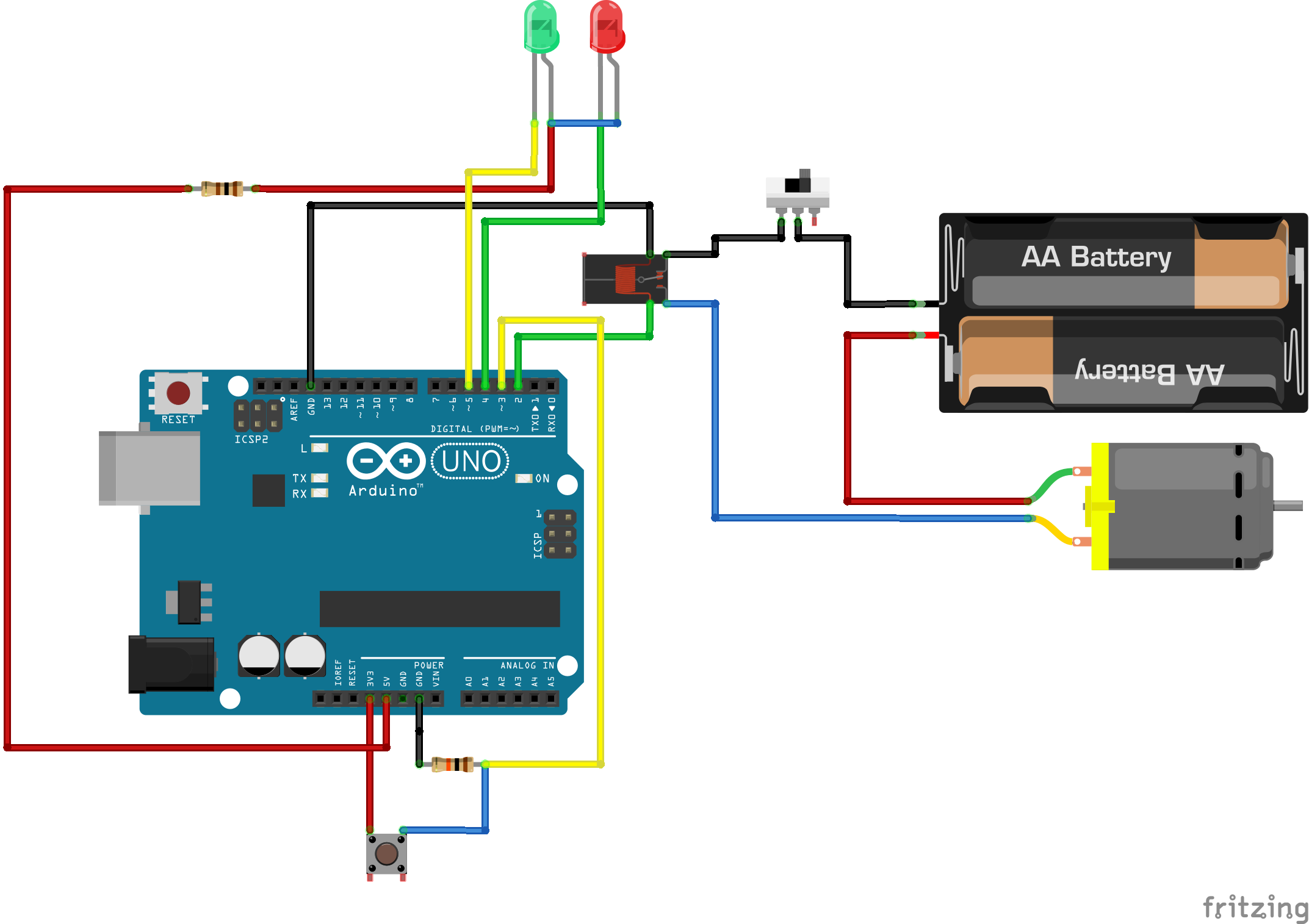
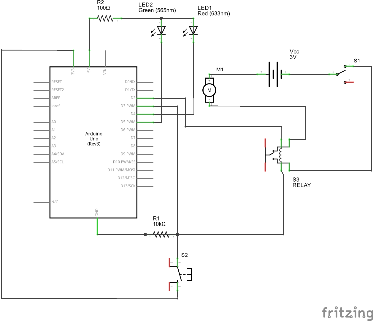
Build the following circuit:
Click the link below to download a PDF containing the circuit diagram and instructions to build it (the PDF file can also be found in the GitHub repository).
Download Circuit Diagram and Instructions
Here are images of the components that you will use to build the circuit.
Completed Circuit
Here are images of the completed circuit.
Loading the Sketch
The link below will allow you to download the sketch for this project. Click the link (or right-click) and save the file to your computer.
Load this sketch into the Arduino IDE in the same manner as in the Blinking LED project. After it is loaded compile and run it. The sketch for this project will write output to the serial port so you will need to open the Serial Monitor from the Tools menu (you can press Ctrl-Shift M).
The Circuit
This project is really two circuits in one. The first circuit monitors the push button and waits for it to be pressed. When the switch is open, the Arduino pin D3 is connected to ground through the resistor R4. Reading the value of this pin will return the value LOW. When the button is closed (pressed), the D3 pin is connected to 3V3 directly and the circuit between 3VS and ground is completed through the resistor R4. We use a high resistance of 10K here to limit the current flow. If we did not put a resistor here or we put a value too small we would short the Arduino power supply and cause the Arduino to shut down or restart.
The second circuit uses a relay to turn a motor connected to a battery on and off. The relay and battery are required because the Arduino cannot push enough current to run the motor on its own. The relay is a switch that is activated by current from another isolated circuit. The relay in this circuit is connected to an Arduino digital port that will activate and deactivate the relay. When the relay is activated, the circuit connecting the battery to the lamp is closed and the motor turns on. When the relay is deactivated the circuit is open and the motor turns off.
The Software
The software will monitor the value of pin D3. When the pin is low the software ignores it and does nothing. When the pin goes HIGH (the button is pressed) the software changes a flag to indicate the button was pushed and starts both the motor and the count down using the LED's. The count down is a flashing of the red LED three times, and finally, the green LED is turned on for one second and the motor is turned off.


Comments
Please log in or sign up to comment.