


Hardware components | ||||||
 |
| × | 1 | |||
 |
| × | 1 | |||
 |
| × | 1 | |||
 |
| × | 1 | |||
Software apps and online services | ||||||
| ||||||
Hand tools and fabrication machines | ||||||
| ||||||
Snap Circuits® makes learning electronics easy and fun! Learn how to use integrate Snap Circuits® with your hardware. Fun for kids!
Introduction ProjectIf you have not completed the introduction please go to the Snap Circuits - Introduction project. This project also contains a complete index of Snap Circuit projects.
Let's Get StartedProject ObjectiveTo show how to use a Photon and Tinker to turn an LED on and off from your smartphone.
Building the CircuitThe minimum set requirement for this project is SC-100.
Click the link below to download a PDF containing the circuit diagram and instructions to build it (the PDF file can also be found in the GitHub repository).
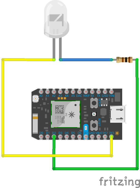
Here are images of the components that you will use to build the circuit.
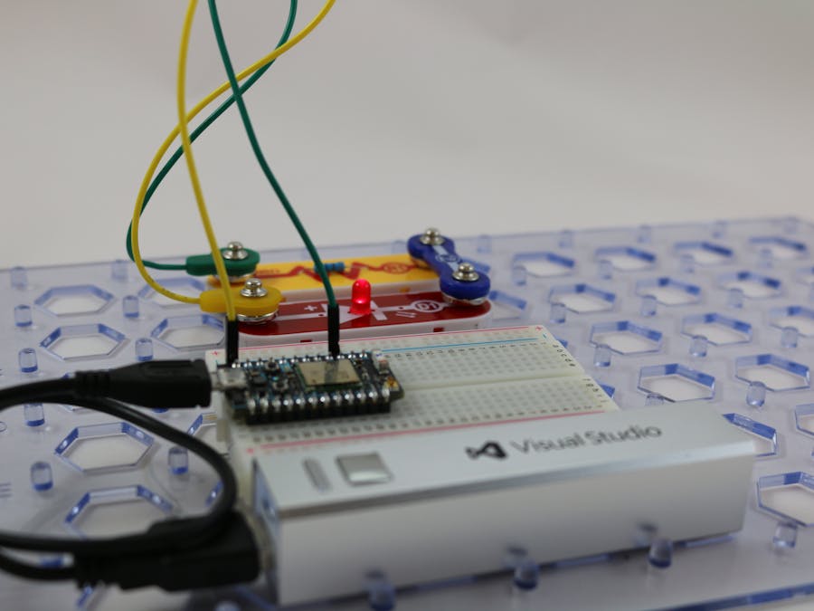
Here are images of the completed circuit.
TIP: Powering the Photon can be done using a micro USB power supply or with a micro USB cable connected to your computer. What's great about this device is that is does not use a lot of power. You can also make your circuit portable by using one of those small USB charging devices to power the circuit. Below are some images of the USB charger I use. These chargers come in a variety of shapes and sizes and can be very inexpensive.How this WorksThe Circuit
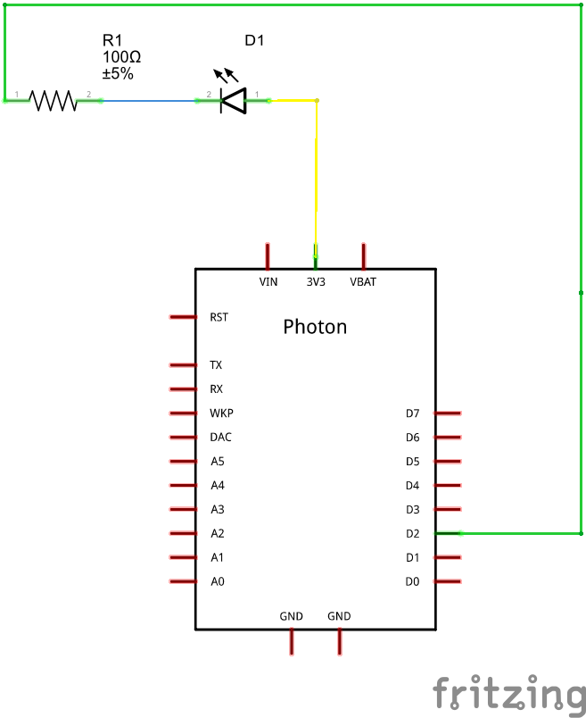
The resistor R1 in the component helps restrict the amount of current that flows into the LED and helps to prevent the LED from burning out by getting too much current.
The LED D1 has a anode and a cathode. The anode end of the LED (this is the end marked +) is connected to the 3.3V (three point three volt) source on the Arduino. The cathode end of the LED is connected to pin 2 on the Arduino through the resistor R1. An LED can only allow current to pass in on direction, and when the current passes in the correct direction, it will produce light.
When the output voltage of pin D2 is set to LOW (0V) the LED is on because the potential difference between these two pins 3.3V. When the D2 is set to HIGH (0V) the LED turns off because the potential difference between these two pins is more than 0V.
TinkerStart the Tinker application by Particle on your smartphone and use the application to control the device. I have included some images of the application running on my iPhone.
- Disconnect the pin end of the yellow wire from the 3.3V pin on the Photon and connect it to the GND pin on the Photon. Now use the Tinker application on your smartphone to change the pin between HIGH and LOW. Does the LED work? Why not?
- Turn the LED around so that the end marked + is next to the resistor R1. What behavior has changed? Can you explain why the LED now turns on and off the opposite as before (turns on when the output is HIGH and of when the output is LOW)?


Comments
Please log in or sign up to comment.