Follow the Snap Circuits platform!
OverviewWhat Are Snap Circuits?
Snap Circuits® makes learning electronics easy and fun! Learn how to integrate Snap Circuits® with your hardware. Fun for kids!
Introductory Project
If you haven't already, check out the Snap Circuits - Introduction project to get aquainted to this platform. This project also contains a complete index of Snap Circuit projects.
Let's Get StartedProject Objective
To show how to use a Photon and Tinker to trigger different sounds from your smartphone.
Building the Circuit
The minimum set requirement for this project is SC-100.
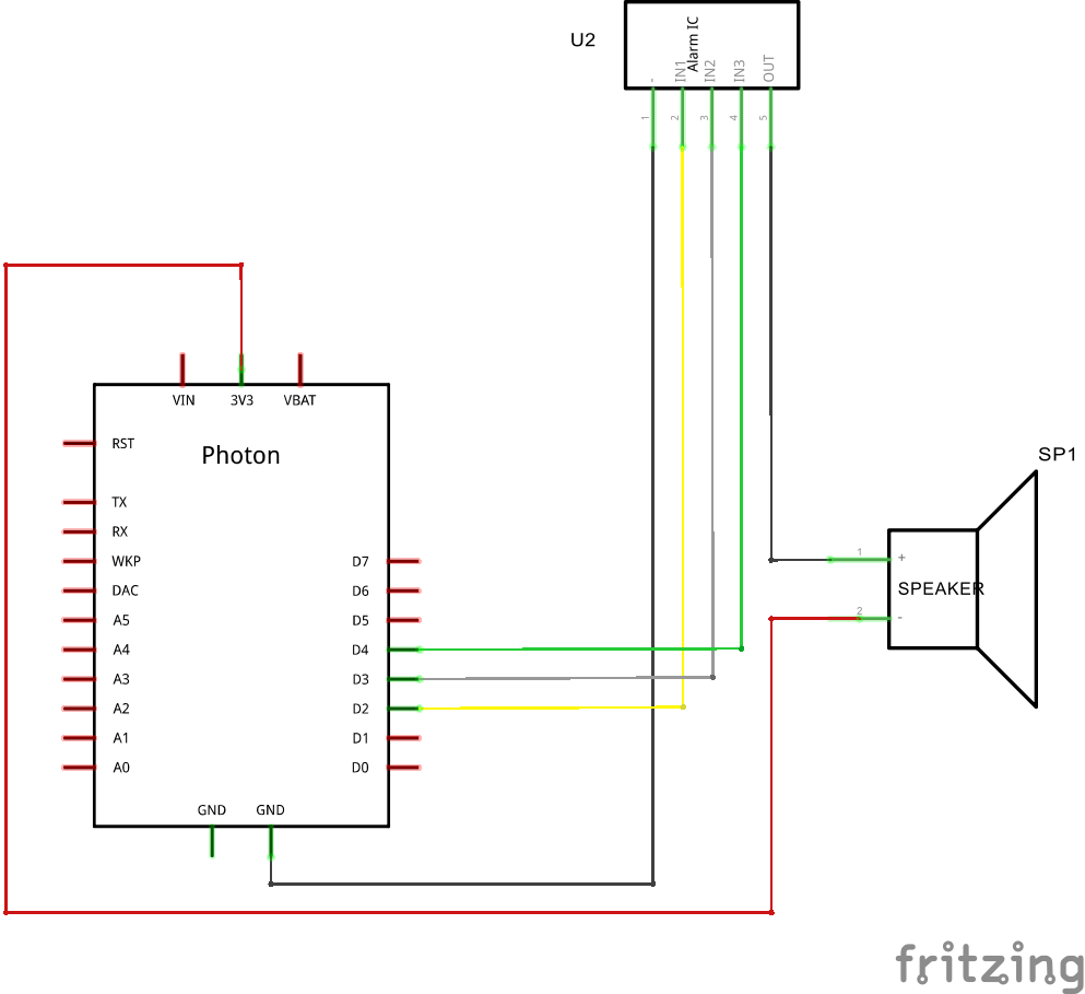
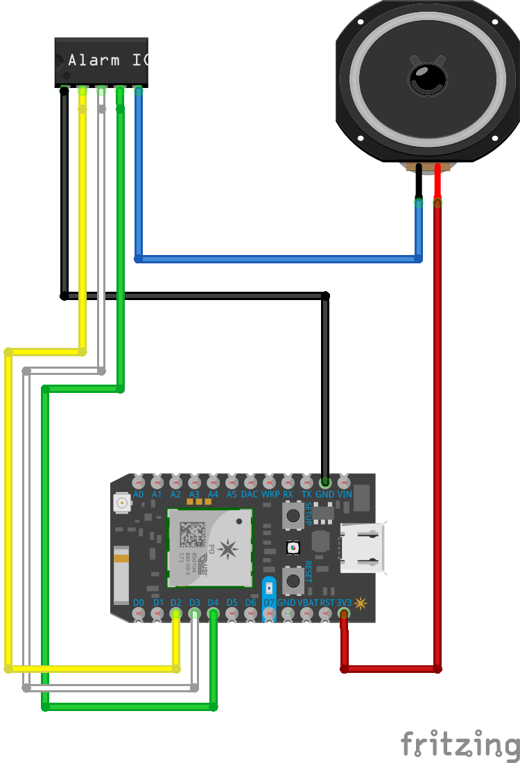
Build the following circuit:
Click the link below to download a PDF containing the circuit diagram and instructions to build it (the PDF file can also be found in the GitHub repository).
Download Circuit Diagram and Instructions
Here are images of the components that you will use to build the circuit.
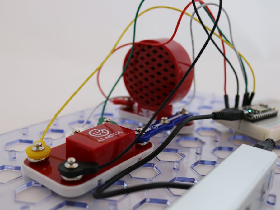
Here are images of the completed circuit.
TIP: Powering the Photon can be done using a micro USB power supply or with a micro USB cable connected to your computer. What's great about this device is that it does not use a lot of power and it can be made portable by using one a small USB charging device to power the circuit. Below are some images of the USB charger I use. These chargers come in a variety of shapes and sizes and are usually inexpensive.How This WorksThe Circuit
The Alarm IC (U2) is capable of playing five different sounds. The speaker is connected between the 3V3 pin of the Photon and the OUT pin on U2. The - (minus) pin on U2 is connected to the GND pin on the Photon. Applying a positive voltage of 3.3V across the three input pins, INP1, INP2 and INP3 will create the different sounds. By connecting each of these three pins on U2 to three different digital ports on the Photon, we can vary the sound that is generated from the IC.
Start the Particle Tinker application by on your smartphone and use it to control the device. I have included some images of the application running on my iPhone.
See how many different sounds you can get by varying the output value of each of the pins (D2, D3 and D4).
Things to Try- The outputs of pins D2 and D3 can also be set to analogWrite. You can change these inputs by pressing the Back arrow in the application, then selecting your Photon again. Set these two pins to analogWrite, then adjust the slider to see what happens. Once you have set the pins back to digitalWrite, your are finishedSet the pins back to digitalWrite when you are finished.
- The Alarm IC can produce five sounds. Vary the state of each pin between HIGH and LOW and try to determine what combination is required for each of the sounds. HINT: Get a piece of paper and a pencil and create a chart like the one shown below; write the value HIGH or LOW in each square.
NOTE: In some cases you may not be able to get all five sounds from the IC. This is because the Photon puts out just enough current to trigger the sounds. Don't worry, your IC is not broken. There are more projects coming that will get all of the sounds!


Comments
Please log in or sign up to comment.